HIGHWAY QUALITY TEST

Precision Testing. Proven Quality. Safer Infrastructure.

Methodology for Structural Concrete for Bridges and Culverts

Methodology for Structural Concrete for Bridges and Culverts 1. Scope The work shall consist of producing and placing concrete of grade M15 and higher by weigh batching in accordance with MoRTH Specifications, IRC:112, approved drawings, and contract specifications. 2. Reference Contract Agreement IRC: SP: 84-2014 MoRTH Specifications (5th Revision) IRC: 112 Relevant Drawings 3. Setting Out After completion of site preparation, alignment of the structure shall be marked on the ground using lime and string. Structural points such as abutment walls and wing walls shall be pegged accurately. Temporary Bench Marks (TBM) shall be established nearby for level reference and protected throughout construction activities. 4. Materials 4.1 Cement Cement conforming to IS:269 shall be used after ensuring the required design strength. Manufacturer Test Certificates (MTC) shall be submitted to the AE for every consignment. Independent testing shall also be conducted at approved laboratories. 4.2 Coarse Aggregate Coarse aggregates shall be obtained from approved quarries and shall consist of clean, hard, durable crushed stone conforming to Table 1700-7 of MoRTH Specifications / IS 383. 4.3 Fine Aggregate Fine aggregates shall be clean, durable, and free from deleterious materials. Gradation shall conform to Table 1000-2 of MoRTH Specifications / IS 383. 4.4 Water Water used for mixing and curing shall conform to IS 456 and Section 1010 of MoRTH Specifications. Water shall be free from harmful substances. Use of seawater shall not be permitted. 4.5 Reinforcement Steel Reinforcement steel shall conform to Section 1009.3 of MoRTH Specifications and IS 1786. TMT Fe-500 grade bars shall be used as per approved drawings. 4.6 Bending of Reinforcement Bar Bending Schedule (BBS) shall be prepared and submitted for approval before commencement of work. It shall include shape, number, cutting length, and weight of bars including auxiliary reinforcement. All materials shall be approved by the AE before use in construction. 5. Placing of Reinforcement Reinforcement shall be placed as per approved drawings and inspected by the AE before concreting. Bars shall be tied using 1 mm binding wire. Cover blocks of the same concrete grade shall be used. Spacer bars and chairs shall be provided to maintain spacing and cover. Horizontal reinforcement shall be adequately supported to avoid sagging. 6. Proportioning of Concrete Concrete shall be produced using approved design mix by weigh batching. Measuring equipment shall be maintained in proper condition and calibrated periodically. Water-cement ratio shall be maintained considering moisture content of aggregates and weather conditions. 7. Trial Mixes Trial mixes for all grades of concrete shall be carried out at the site laboratory before commencement of work using approved materials. Additional trial mixes shall be conducted whenever there is a change in source or proportion of materials. 8. Equipment Batching Plant Transit Mixer Concrete Pump Vibrators & Vibrator Needles Wheel Loader Excavator Shuttering Material Bar Bending & Cutting Machine 9. Transporting, Placing & Compaction of Concrete Concrete shall be transported using transit mixers or concrete pumps. The delivery pipeline shall have minimum bends. Concrete temperature during placing shall be between 5°C and 40°C. Concrete shall be compacted within 30 minutes of discharge. Concrete shall be placed in layers not exceeding 300 mm compacted thickness. Fresh concrete shall not be placed against concrete older than 30 minutes without proper construction joints. Concreting shall not be carried out when ambient temperature exceeds 40°C. 10. Formwork Formwork shall conform to Section 1500 of MoRTH Specifications and IRC:87. Only steel formwork shall be used. Formwork shall be rigid and true to shape. Damaged formwork shall not be used without repair. Steel tubes used as supports shall have minimum 4 mm wall thickness. 11. Construction Joints Construction joints shall be kept to a minimum and provided as per drawings. Laitance shall be removed and the concrete surface roughened before placing fresh concrete. 12. Curing Water curing shall be carried out using approved water conforming to MoRTH Specifications. Concrete surfaces shall be kept continuously wet. Wet hessian cloth, sacks, or canvas may be used. Curing shall continue for at least 14 days after concreting. 13. Finishing Finishing shall be carried out as per Clause 1713 of Section 1700 of MoRTH Specifications to achieve smooth and durable concrete surfaces.

Methodology for Structural Concrete for Bridges and Culverts Read More »

Structure
Methodology for Pre-stressing of HTS Strands

Methodology for Pre-stressing of HTS Strands This item of work deals with the activity of Pre-stressing of H.T.S strands of PSC girders with approved materials as per the specifications of the Contract Agreement. General This item of work shall be carried out in compliance with Clause 1800 of MoRTH Specifications. The materials shall conform to Section 1000 and the grout mix shall conform to Section 1808 of MoRTH Specifications. Procedure 1. Cable Fabrication & Laying The length of cable required shall be computed from the drawing including allowances for profiling and gripping length of jack. The strand shall be cut evenly using an abrasive cutter to the required length. Both ends of the cable shall be numbered to maintain correct configuration in the bearing plate and prevent twisting in the duct. The duct shall be profiled as per approved ordinates and cable shall be threaded manually into the duct. Grout vents shall be provided wherever required. Tube ducts of the anchorage shall be fixed with end blocks as shown in drawings. The ducts shall be connected to tube units. The cable consisting of the specified number of strands shall be tied with binding wire at regular intervals and threaded into sheathing. Both ends of the duct shall be closed after strand installation and protruding strands shall be wrapped properly to avoid dirt entry during concreting. 2. Concreting During concreting, cables shall be moved manually at suitable intervals to avoid concrete blockage inside ducts. The strands beyond the bearing plate shall be cleaned using petrol after concreting to remove dust and rust. 3. Stressing Operation Stressing of cables may be carried out from both ends. Bearing plates shall be cleaned and fixed in proper configuration. Wedges shall be fixed to bearing plates and tightened. Jacks shall be mounted properly and aligned with the cable. Master grips of the jack shall be inserted over strands and fixed into pulling plates. Stressing pumps shall be connected to jacks through hose pipes. Correction factor shall be calculated from pressure and elongation readings. Initial pressure of 50 kg/cm² shall be applied to remove cable slackness. Pressure shall then be increased gradually and elongation readings recorded. Tensioning force shall be verified by pressure gauge readings and elongation comparison. Acceptance Criteria During Stressing If calculated elongation is achieved before specified pressure, stressing shall continue till specified pressure is reached provided elongation does not exceed 1.05 times calculated elongation. If specified pressure is reached before calculated elongation, stressing may continue in intervals of 5 kg/cm² provided pressure does not exceed 1.05 times specified pressure. If elongation remains less than 0.95 times calculated elongation at 1.05 times specified pressure: Check functioning of jack, pump and hose pipes. Detension the cable and check for duct blockage. On achieving full load, wedges shall be locked hydraulically. Jack shall be released and retracted. The same procedure shall be repeated for all cables. 4. Grouting All protruding ends of strands shall be cut after prestressing. Nozzles and valves shall be fitted to grout holes. Ducts shall be flushed with lime water before grouting. Grout shall be prepared using Ordinary Portland Cement and non-shrink grout admixture. Grouting shall commence with low pressure until grout flows out from the other end. The outlet shall be closed once grout consistency becomes uniform. After achieving desired pressure, inlet valve shall be closed. Equipment / Machinery Hydraulic Jack Pressure Gauge Compressor Grouting Equipment Grout Cube Moulds Tolerances Parameter Permissible Tolerance Variation from specified horizontal profile ±5 mm Variation from specified vertical profile ±5 mm Variation from specified position in member ±5 mm “`

Methodology for Pre-stressing of HTS Strands Read More »

Structure

Methodology for Box Culverts

Methodology for Box Culverts 1. Reference Drawings of Box Culverts Reviewed drawings shall be referred to for casting of box culverts. 2. Working Drawings Working drawings, structural drawings, and relevant details shall be submitted to the AE prior to commencement of work for approval. After approval, setting out of the structure shall be carried out at site. 3. Scope of Work The work shall consist of widening of existing box culverts or reconstruction/construction of new box culverts as per reviewed drawings. The work includes: Excavation Foundation Preparation PCC & Raft Construction Wall Construction Deck Slab Construction Return Wall & Curtain Wall Construction Apron & Protection Works 4. Reference Contract Agreement IRC: SP: 84-2014 MoRTH Specifications (5th Revision) Relevant Approved Drawings 5. Plant & Machinery Mixer Machine with Weigh Batcher / Batching Plant Transit Mixer Concrete Vibrator & Hand Rammer Trailer / Open Body Truck Water Tanker Water Pump Shuttering Plates & Staging Materials Backhoe Loader / Excavator 6. Materials Cement, mineral admixtures, chemical admixtures, fine aggregates, coarse aggregates, and water shall conform to Clause 1700 of MoRTH Specifications. Reinforcement steel shall be HYSD Fe-500 grade bars conforming to IS:1786 or as shown in approved drawings. Concrete grade shall be as specified in reviewed drawings. Concrete shall be produced, transported, and placed as per approved mix design. 7. Method of Construction Excavation shall be carried out manually or mechanically depending upon site conditions. Care shall be taken to avoid over-excavation. The PCC bed level shall be maintained accurately. If required, the foundation surface shall be sprinkled with water before laying PCC. Layout marking shall be carried out for raft and walls. PCC of grade M15 or as shown in approved drawings shall be laid over prepared foundation. Concrete grades for raft, walls, deck slab, return wall, and curtain wall shall be as per reviewed drawings. Reinforcement steel shall be fixed and tied as per approved BBS and drawings. Formwork for raft including haunch and kick-starter shall be erected properly. Concreting shall be carried out as per Clause 1700 of MoRTH Specifications. Post-concreting inspection shall be carried out after de-shuttering and any defects shall be rectified immediately. Proper curing arrangements shall be ensured after concreting. The same sequence shall be followed for walls, return walls, and curtain walls. Weep holes shall be provided as per approved drawings. Scaffolding and soffit formwork for top slab shall be erected properly. Deck slab reinforcement shall be tied as per approved BBS and drawings. Concreting of top slab shall be carried out after inspection approval. Boulder pitching and apron protection works shall be executed on upstream (U/S) and downstream (D/S) sides. If total wall height is less than 3 m, slab shall be cast monolithically along with walls after casting starter and haunch. Side shutters of wall and deck slab may be removed after 12 hours of concreting or as approved by the Engineer. Proper curing of deck slab and wall surfaces shall be carried out by ponding and wet hessian cloth covering. Soffit staging shall be removed after achieving required strength and as per span criteria. Floor protection works on U/S and D/S sides shall be carried out as per GFC drawings. Traffic diversion arrangements shall be made before commencement of work to ensure safe and smooth vehicular movement. 8. Quality Control Sampling and testing frequency shall be carried out as per MoRTH Clause 1700 and IS:4926-2003 requirements. Concrete Cube Testing Slump Test Reinforcement Inspection Formwork Inspection Line, Level & Alignment Check Cover Measurement 9. Safety All construction vehicles and equipment such as transit mixers, JCBs, and excavators shall have functional reverse horns and safety systems. Excavated areas shall be properly barricaded using safety tapes, caution boards, and barricading arrangements. Workers shall use PPE such as helmets, safety shoes, reflective jackets, gloves, and safety belts. Proper illumination and warning signs shall be provided during night work. Traffic management and diversion arrangements shall be maintained throughout the construction period.

Methodology for Box Culverts Read More »

Structure

Methodology for Pipe Culverts

Methodology for Pipe Culverts 1. Scope The work shall consist of furnishing and installing the required length, type, and size of reinforced cement concrete pipes at locations shown in the drawings or as directed by the Contract Agreement (CA). 2. Reference Contract Agreement IRC: SP: 84-2014 MoRTH Specifications (5th Revision) Relevant Approved Drawings 3. Setting Out After completion of site clearance, alignment of the culvert shall be surveyed and marked on the ground using lime and string for locating the culvert and associated structures. Temporary Bench Marks (TBM) shall be established near the structure location for construction reference. TBM locations shall be selected carefully to avoid disturbance during construction activities and shall remain intact until completion of the work. 4. Working Drawings Working drawings, structural drawings, and relevant details shall be submitted to the AE before commencement of work. After review and approval by the AE, setting out of the structures shall be carried out. 5. Selection of Materials All materials used in pipe culvert construction shall conform to Section 2900 of MoRTH Specifications. RCC pipes shall be inspected and approved by the AE before use. Manufacturing test certificates shall be submitted for approval. PCC, RCC, aggregates, and jointing materials shall conform to approved specifications. 6. Equipment & Machinery Hydraulic Excavator Hydraulic Crane / Hydra Dumper Plate Compactor Mechanical / Pneumatic Tampers Water Tanker Tractor Trolley 7. Method of Operation Foundation bed for pipe culverts shall be excavated true to the lines and grades shown in approved drawings or as directed by the AE. Pipes shall be laid either in shallow excavation of natural ground or in trenches cut through existing embankment to required levels. Where trench excavation is required, trench width shall be maintained at a minimum of 150 mm or one-fourth of pipe diameter on either side, whichever is greater, but not exceeding one-third of pipe diameter. Sides of trenches shall be kept as vertical as possible and pipes shall be laid on PCC bedding. The bedding surface shall provide a firm and uniform foundation throughout the culvert length at required line, level, and grade. After completion of bedding, pipes shall be carefully laid to the required line and level without damage and as approved by the AE. Where multiple pipes are laid, minimum clear spacing between pipes shall be half the pipe diameter or minimum 500 mm. Pipe laying shall commence from the outlet side (downstream) towards the inlet side (upstream) to ensure smooth invert alignment. In bell-mouth pipes, the belled end shall face upstream direction. Pipe joints shall be made as per approved drawings and specifications. For light hydraulic pressure joints, recesses at pipe ends shall be filled with jute braiding dipped in hot bitumen or approved compound. Bitumen rings shall be properly compressed by jacking or suitable approved methods to ensure watertight joints. All joints shall be finished flush with the internal pipe surface and kept damp for at least four days after completion. Backfilling shall commence only after jointing materials have adequately hardened. Backfill material shall be clean and free from boulders, roots, organic matter, and oversized lumps. Backfilling shall be carried out equally on both sides of the pipe to avoid unequal pressure. Backfill shall be placed in layers not exceeding 150 mm thickness and compacted thoroughly using approved compaction equipment. Special attention shall be given to compaction around the haunch portion of the pipe. Head walls, wing walls, aprons, and ancillary works shall be constructed as per approved drawings and relevant MoRTH sections. RCC works shall conform to Sections 1500, 1700, 2100, 2200, or 2300 as applicable. Apron and protection works shall conform to Section 2500 of MoRTH Specifications. 8. Opening to Traffic Traffic shall be allowed over the pipe culvert only after providing a minimum earth cushion of 600 mm above the top of the pipe or as specified in approved drawings. 9. Quality Control Checking of Line, Level & Alignment Inspection of Bedding & PCC Pipe Joint Inspection Compaction Testing of Backfill Material Testing as per MoRTH Specifications Inspection of Headwall & Protection Works 10. Safety All machinery and lifting equipment shall be inspected before use. Barricading and caution boards shall be provided around excavation areas. Workers shall wear PPE such as helmets, safety shoes, reflective jackets, gloves, and masks. Proper traffic diversion and warning signs shall be maintained throughout the construction period. Safe lifting practices shall be followed during pipe handling and placement.

Methodology for Pipe Culverts Read More »

Structure

Methodology for Slab Culverts and Minor Bridges

Methodology for Slab Culverts and Minor Bridges 1. Scope The work shall consist of Reinforced Cement Concrete (RCC) works and furnishing of structures for slab culverts and minor bridges at locations shown in approved drawings or as instructed by the Engineer, in accordance with MoRTH Specifications. 2. Reference Contract Agreement IRC: SP: 84-2014 MoRTH Specifications (5th Revision) Relevant Approved Drawings 3. Setting Out After completion of site preparation, alignment of slab culverts or minor bridges shall be marked on the ground using lime and string. Locations of wing walls, return walls, abutments, and other structural components shall be pegged accurately with reference to the approved alignment. Temporary Bench Marks (TBM) shall be established near the structure location for construction reference. The TBM location shall be selected carefully to avoid disturbance during construction activities and shall remain intact until completion of the structure. 4. Working Drawings Working drawings, structural drawings, and relevant details shall be submitted to the AE before commencement of work. After review and approval by the AE, setting out of the structures shall be carried out. 5. Selection of Materials 5.1 Formwork All formwork materials shall conform to IRC:87 requirements. Only steel formwork shall be used. All bolts shall be countersunk. Approved internal ties and plastic spacers shall be used. Structural steel tubes used for staging shall have minimum wall thickness of 4 mm. 5.2 Reinforcement Reinforcement shall consist of TMT Fe-500 grade steel bars conforming to IS:1786 and approved drawings. Only uncoated steel reinforcement shall be used. Steel shall conform to approved specifications and drawings. 5.3 Concrete & Brick Concrete, brick, and other construction materials shall conform to Section 1000 of MoRTH Specifications. 6. Equipment & Machinery Batching Plant Transit Mixer Concrete Vibrator & Needles Wheel Loader Excavator Shuttering Materials Bar Bending & Cutting Machine Concrete Pump Hydraulic Crane Water Tanker Tractor Trolley 7. Method of Operation 7.1 Formwork a. Design of Formwork Complete design and drawings of formwork for slab superstructure shall be submitted for approval before commencement of work. Formwork design shall conform to IRC:87. b. Workmanship Workmanship shall comply with Clauses 1504.2, 1504.4, and 1504.10 of MoRTH Specifications. Formwork shall produce concrete true to shape, line, level, and dimensions. Steel tubes used in staging shall be free from bends and defects. Staging shall rest on firm foundations considering subsoil conditions. c. Preparation of Formwork Before Concreting Contact surfaces shall be cleaned and dried before application of release agent. Approved water-based release agent shall be used. Release agent shall not come into contact with reinforcement or hardened concrete. Excess release agent shall be wiped off properly. d. Removal of Formwork De-shuttering and de-centering procedures shall be planned in advance and submitted to the AE for approval. Formwork shall not be removed without prior approval. 7.2 Reinforcement a. Bending of Reinforcement Bar Bending Schedule (BBS) shall be prepared and submitted for approval before start of work. BBS shall include bar mark, shape, cutting length, quantity, and weight. Separate schedules shall be prepared for spacers and chairs. b. Placing of Reinforcement Reinforcement shall be placed as per approved drawings and inspected by the AE before concreting. Bars shall be tied securely using binding wire to avoid displacement during concreting. Cover blocks shall be made from cement, sand, and aggregate of the same durability as surrounding concrete. Spacer bars shall be provided at approximately 1 m intervals. Minimum spacer diameter shall be 12 mm or equal to the largest main reinforcement diameter, whichever is greater. Auxiliary supports such as spacers, chairs, and blocks shall be used to maintain reinforcement position. 8. Concrete 8.1 Grades of Concrete Concrete used in structures shall be Design Mix Concrete of approved grade as specified in drawings. 8.2 Proportioning of Concrete Concrete batching shall be carried out using computerized batching plants. Measuring equipment shall be maintained in clean and serviceable condition and calibrated periodically. 8.3 Water Cement Ratio Water-cement ratio shall be maintained considering moisture content of aggregates and weather conditions. 8.4 Admixtures Approved admixtures conforming to IS:6925 and IS:9103 may be used with prior approval of AE. Admixtures containing chlorides, sulphides, sulphates, nitrates, or harmful materials shall not be used. Hydrogen or nitrogen generating admixtures shall not be permitted. 8.5 Size of Coarse Aggregate Maximum size of coarse aggregate shall conform to Table 1700-7 of MoRTH Specifications. 9. Transporting, Placing & Compaction of Concrete Concrete shall be transported using transit mixers and placed using concrete pumps or suitable chutes. Pipeline routing shall have minimum bends. Concrete temperature during placing shall be maintained between 5°C and 40°C. Concrete shall be compacted within 30 minutes of discharge. Concrete shall be placed in horizontal layers not exceeding 300 mm compacted thickness. Fresh concrete shall not be placed against concrete older than 30 minutes without proper construction joints. Concreting shall not be carried out when ambient temperature exceeds 40°C. 10. Protection & Curing Concrete surfaces shall be protected and cured immediately after placement. Surfaces shall be kept continuously wet by ponding or covering with wet hessian cloth, canvas, or sacks. Curing shall continue for a minimum period of 14 days. 11. Quality Control Inspection of Reinforcement & Cover Formwork Inspection Concrete Slump Test Cube Casting & Testing Line, Level & Alignment Checks Inspection of Bearings & Expansion Joints (if applicable) 12. Safety All equipment and machinery shall be inspected before use. Workers shall use proper PPE such as helmets, reflective jackets, gloves, and safety shoes. Barricading and caution boards shall be provided around work areas. Proper scaffolding and safe working platforms shall be ensured during slab construction. Traffic diversion and warning signage shall be maintained throughout construction activities.

Methodology for Slab Culverts and Minor Bridges Read More »

Structure
Consistence-cement

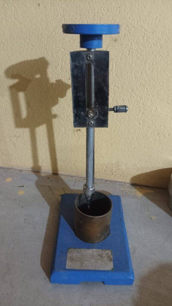
Consistency of Cement | Standard Consistency Test (Vicat Apparatus)

The cement consistency test is performed to determine the standard water content required to achieve a paste of normal consistency, which is crucial for ensuring optimum hydration of cement, achieving desired strength & workability in concrete and mortar.
• Preventing excess bleeding or shrinkage.

Consistency of Cement | Standard Consistency Test (Vicat Apparatus) Read More »

Cement
soil.jpg

Soil Testing

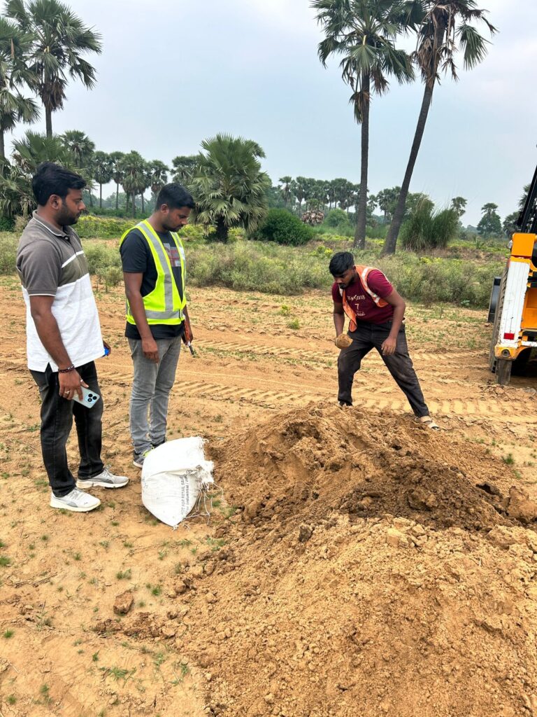
Soil Testing for Highway Construction | MoRTH & IS Standards – Complete Guide Soil Testing for Highway Construction – Complete Quality Control Guide Soil testing forms the backbone of highway construction quality control. The strength, compaction, and durability of soils directly affect pavement performance, embankment stability, and long-term maintenance costs. Without proper soil testing, highways are prone to settlement, rutting, cracking, and premature failure. This comprehensive guide covers all soil tests required in highway projects as per MoRTH (5th Revision) and IS 2720. Each test includes purpose, procedure, acceptance criteria, and field relevance, with frequency guidelines as per MoRTH Clause 900. 1. Importance of Soil Testing in Highway Construction Highway pavements transmit heavy traffic loads to the underlying soil layers. If the soil lacks adequate strength, compaction, or moisture control, structural distresses appear early, increasing maintenance costs. Ensures construction meets design assumptions Controls moisture and compaction during placement Verifies suitability of borrow materials Supports quality assurance and payment certification Reduces risk of pavement failure and expensive repairs 2. Applicable Standards & References MoRTH Specifications (5th Revision) IS 2720 – Methods of Test for Soils (Parts 1–40) IRC:37 – Guidelines for Embankment & Subgrade IRC:SP:84 – Soil Quality Control Practices Project Technical Specifications 3. Classification of Soil Tests in Highway Works A. Field Tests Field Density Test (Sand Replacement / Core Cutter) In-situ Moisture Content Visual Inspection & Classification of Borrow Material B. Laboratory Tests Grain Size Analysis Atterberg Limits Proctor Compaction Test (Modified / Standard) California Bearing Ratio (CBR) Test Free Swell Index Moisture Content Verification 4. Mandatory Soil Tests & Their Purpose Test Purpose MoRTH Reference Field Density Test Verify achieved compaction on site Clause 903, 305 Modified Proctor Test Determine MDD & OMC IS 2720 (Part 8) CBR Test Assess load-bearing capacity Clause 305, 903 Atterberg Limits Evaluate plasticity & volume change IS 2720 (Part 5) Grain Size Analysis Soil gradation & classification IS 2720 (Part 4) Free Swell Index Check expansive soil behavior IS 2720 (Part 40) Moisture Content Verify optimum moisture for compaction IS 2720 (Part 2) 5. Acceptance Criteria (Key Requirements) Parameter Requirement Field Density – Embankment ≥ 95% of MDD Field Density – Subgrade ≥ 97% of MDD Moisture Content OMC ± 2% CBR (Subgrade) As per design (typically ≥ 8%) Free Swell Index ≤ 50% Atterberg Limits Plasticity Index within project limits 6. Field Quality Control Procedures Quality control is continuous. Before placing any layer, soil moisture is adjusted to OMC. Compaction is done using approved rollers, followed by immediate density verification. Scarify or remix soil if density is below required Adjust moisture content Re-compact and retest Maintain records for all layers 7. Inspection Checklist for Site Engineers ✔ Borrow soil approved by Engineer ✔ Laboratory test reports available ✔ Moisture within OMC range ✔ Layer thickness controlled ✔ Field density test passed ✔ Failed areas rectified and retested ✔ Documentation per MoRTH Clause 903 maintained 8. Detailed Soil Test Procedures by Construction Stage This section organizes soil tests based on construction stage: Original Ground Level (OGL), Embankment, and Subgrade. Each test includes What, Why, and When (MoRTH Clause 900 frequency). 8.1 Original Ground Level (OGL / Borrow Soil) OGL represents the natural ground or borrow material used in embankment construction. Tests here ensure the foundation soil is suitable. Field Density Test – Sand Replacement / Core Cutter What: Measure in-situ density of OGL soil. Why: Ensures soil compaction at natural state meets design assumptions. When: 1 test per 3000 m³ (MoRTH Clause 900). Learn more Grain Size Analysis What: Determine soil particle distribution. Why: Classifies soil for suitability and stability. When: 1 test per 5000 m³ (MoRTH Clause 900). Learn more Atterberg Limits Test What: Determine plasticity and shrink-swell potential. Why: Identifies highly plastic soils that may cause settlement. When: 1 test per 5000 m³ (MoRTH Clause 900). Learn more Free Swell Index Test – Coming Soon Moisture Content Test – Coming Soon Modified Proctor Compaction Test – Coming Soon 8.2 Embankment Layer The embankment is the built-up layer above OGL. Tests ensure proper compaction, layer thickness, and material quality for load-bearing. Field Density Test What: Measure compaction of each embankment layer. Why: Prevents settlement and ensures design strength. When: 1 test per 250 m³ per layer (MoRTH Clause 900). Coming Soon Moisture Content Test What: Ensure soil is at Optimum Moisture Content before compaction. Why: Moisture outside OMC reduces compaction efficiency. When: 1 test per 250 m³ per layer (MoRTH Clause 900). Coming Soon Modified Proctor Compaction Test What: Determine MDD and OMC for embankment soil. Why: Guides compaction process for each layer. When: 1 test per soil type or 10000 m³ (MoRTH Clause 900). Coming Soon CBR Test What: Assess load-bearing capacity of embankment layer. Why: Ensures embankment can support pavement layers. When: 1 test per 5000 m³ (MoRTH Clause 900). Learn more 8.3 Subgrade Layer Subgrade is the topmost soil layer that directly supports the pavement. Quality here is critical for long-term pavement performance. Field Density Test What: Measure density after final compaction of subgrade. Why: Prevents differential settlement and ensures uniform support. When: 1 test per 200 m² (MoRTH Clause 900). Coming Soon Moisture Content Test What: Verify soil moisture is within ±2% of OMC. Why: Ensures optimal compaction for design strength. When: 1 test per 200 m² (MoRTH Clause 900). Coming Soon CBR Test What: Evaluate subgrade strength and pavement design adequacy. Why: Determines structural capacity for traffic loads. When: 1 test per 500 m² (MoRTH Clause 900). Learn more Atterberg Limits / Plasticity Check What: Detect highly plastic soils in subgrade. Why: High plasticity soils may cause swelling, shrinkage, and cracking. When: 1 test per 5000 m³ (MoRTH Clause 900). Coming Soon Free Swell Index What: Measure potential for soil expansion. Why: Prevents distress in subgrade and pavement. When: 1 test per 5000 m³ (MoRTH Clause 900). Learn more 9. Common Site Issues & Rectification Low density → Increase roller passes or adjust moisture content High plasticity → Blend with granular material or use chemical

Soil Testing Read More »

Soil, Structure

Procedure for Sampling & Testing of Incoming Materials (QA/QC Highway Works)

SAMPLING AND TESTING PROCEDURE FOR CEMENT: Check the seal number as per invoice of the browser. If the seal found tight and match with the invoice, then collect a representative sample of 20kg for in-house testing in the presence of client. Conduct the routine test like fineness, % passing on 90 mic sieve and allow for unload, if found complied to IS 4031. The tests like consistency, soundness, compressive strength, initial and final setting of the cement shall be tested as per IS 4031. Prepare formats for above tests and get it signed by client and file the records. Maintain invoice register for cement receipt at plant. Ensure all the tests shall be performed as per week number of the cement. SAMPLING AND TESTING OF REINFORCEMENT: Once the reinforcement lots arrived to site from approved sources, unload the material in stacking yard. Inspect the reinforcement lot as per invoice and ensure tagging of reinforcement for every lot. Collect 2 samples (3 pieces of 1m length for each sample) from every dia of reinforcement for a lot of 50t and 3 samples for 100MT. Bring the cutting pieces to lab and in the sampling register. Check the weight per running meter for the samples collected. Rolling margin of all samples shall be collected for every lot. If the rolling margin found within the tolerable limits as per IS 1786-2008, accept the lot. Otherwise inform to supplier to take back the lot. Invoice with test certificate shall be verified by quality in charge and sign on test certificate. Enter the details of reinforcement received in the invoice register and get the signature of client. If any lot required for independent lab testing, raise RFI and collect the samples in the presence of client. Sign the sample card by client and IE representatives and keep one copy in lab and other copy to tie for sample pieces. Physical and chemical properties of the reinforcement tested in independent lab shall be reviewed by quality in charge and client and ensure complied to IS 1786-2008. The test reports of independent lab will be submitted to client for review and approval. SAMPLING AND TESTING OF FINE AGGREGATE: Once the fine aggregate (river sand) load received at site from approved source, collect a representative sample of 20kg for lab testing to check physical properties. Enter the details of river sand in the sampling register. The material shall be tested for sieve analysis and check for zone of the sand and Fineness Modulus (FM). Check the silt content of the sand as per IS 2386. If the sand falls in zone-II and the FM lies in between 2 to 3.5 and the silt content less than 3% , the vehicle shall be allowed for unloading . If the sand doesn’t meet the above requirements (FM and silt content) shall be rejected. If the sand contains over size material more than 10% on 10mm sieve shall be screened and use for permanent works. Independent lab testing of sand shall be tested as per approved ITP. SAMPLING AND TESTING OF BITUMEN: Once the bitumen tanker arrived at site, verify the invoice number and seal of the tanker. Collect the sample with sampler of weight not less than 1 kg. Enter the sample details in sampling register and sample number shall be given. Test the sample for absolute viscosity, softening point, and penetration. If the test results found satisfactory, allow the tanker for unload. Review the conducted test results and compare with MTC. Prepare the test reports and get it signed by client and file the records. Maintain the invoice register for incoming bitumen and get the signature in theregister by client. The sample shall be collected for independent lab testing frequency as per theapproved ITP. SAMPLING AND TESTING OF ADMIXTURE: Once the admixture barrels arrived at site, verify the invoice number and batch number of the material. Collect the sample with sampler of weight not less than 2 kg. Enter the sample details in sampling register and sample number shall be given. Test the sample for density at room temperature. If the test results found satisfactory, then allow the admixture to use in permanent work. Review the MTC test results as per IS 9103. Maintain the invoice register for incoming bitumen and get the signature in the register by client. SAMPLING AND TESTING OF EMULSION (SS-1 & RS-1): Once the emulsion tanker arrived at site, verify the invoice number and seal of the tanker. Collect the sample with sampler of weight not less than 1 kg. Enter the sample details in sampling register and sample number shall be given. Test the sample for viscosity by say bolt furl viscometer. If the test results found satisfactory, allow the tanker for unload. Conduct the balance tests like residue test by evaporation. Review the conducted test results and compare with MTC. Prepare the test reports and get it signed by client and file the records. Maintain the invoice register for incoming emulsions and get the signature in the register by client. The sample shall be collected for independent lab testing frequency as per the approved ITP. SAMPLING AND TESTING OF GEO-GRIDS / GEO-TEXTILE: Once the Geogrid material arrived at site, verify the invoice number and grade. Raise the RFI and Collect the sample from bundle I roll of size not less than 2m*2m from each grade. Enter the sample details in sampling register and sample number shall be given. Count the number of ribs in machine direction and transverse direction. The samples shall be tagged with sample card mentioned all the details with signatures of client. The collected samples shall be sent for independent lab testing as per approved ITP. Review the MTC test results as per grade requirement. Maintain the invoice register for Geogrid and get the signature of client. TEST PROCEDURE OF CTSB MIX DESIGN Raise RFI for sampling of aggregates for CTSB Mix Design. Sample the individual aggregates jointly. Do individual gradation for each aggregate as mentioned in MoRTH

Procedure for Sampling & Testing of Incoming Materials (QA/QC Highway Works) Read More »

Soil

QA/QC Starter Guides for Highway Engineers

QA/QC Starter Guides for Highway Engineers 🚧 QA/QC Engineer Starter Guide for Highway Projects ⚡ Quick Summary ✔ Understand QA vs QC ✔ Know your daily site responsibilities ✔ Learn essential QA/QC workflow ✔ Avoid common beginner mistakes A QA/QC Engineer plays a critical role in ensuring that all construction activities meet required quality standards, specifications, and safety requirements. This guide will help you understand your role and daily workflow on highway projects. 🧠 What is QA/QC? Quality Assurance (QA): Planning activities to maintain quality, including method statements, material approvals, and procedures. Quality Control (QC): Execution stage involving testing, inspection, and verification of work. 👉 Simple: QA = Planning | QC = Testing + Execution 👷 Your Role on Site ✔ Conduct material testing (soil, concrete, bitumen) ✔ Perform site inspections (IR/RFI) ✔ Maintain quality documentation ✔ Coordinate with contractor & consultant 📅 Daily Work Checklist (Must Follow) 🔹 Check incoming material quality 🔹 Perform required field/lab tests 🔹 Maintain registers & reports 🔹 Raise Inspection Requests (IR) 💡 Pro Tip: Strong documentation = strong QA system 🎁 Get Free QA/QC Starter Kit Download site formats, calculators & beginner guides Download Free 🔒 Want Full Professional Tools? Get detailed SOPs, Excel formats & advanced calculators Unlock Starter Bundle

QA/QC Starter Guides for Highway Engineers Read More »

FAQ/Interview

© 2026 HIGHWAY QUALITY TEST. All rights reserved.

WhatsAppNeed Help?
Scroll to Top