HIGHWAY QUALITY TEST

Precision Testing. Proven Quality. Safer Infrastructure.

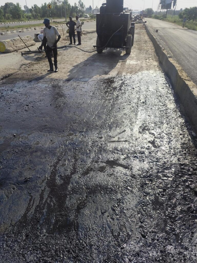
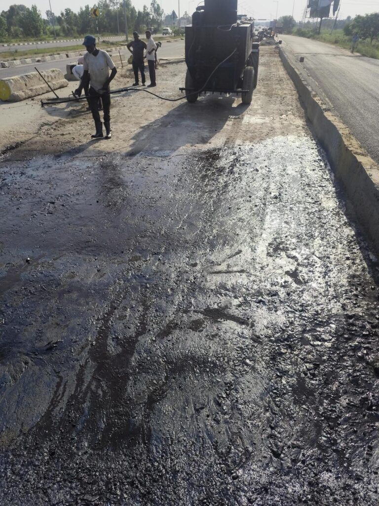
prime coat spraying

Prime Coat

Prime Coat Procedure in Road Construction | Step-by-Step Site Execution (MoRTH Clause 502) The Prime Coat Procedure is one of the most important construction activities in flexible pavement construction. It involves the uniform application of a low-viscosity bituminous binder, generally SS-1 Grade Cationic Bitumen Emulsion, over an approved granular base such as Wet Mix Macadam (WMM), Water Bound Macadam (WBM), or other prepared non-bituminous layers before laying the first bituminous course. A properly executed Prime Coat penetrates the surface voids of the granular base, binds loose particles, minimizes dust, reduces excessive absorption of binder from the overlying asphalt layer, and develops a strong bond between the granular layer and the first bituminous course. The following step-by-step procedure is based on MoRTH Clause 502 and reflects the actual construction practices followed on NHAI, EPC, HAM, BOT, L&T ECC, APCO, Afcons, KNR, Dilip Buildcon, and other highway infrastructure projects. Step-by-Step Prime Coat Procedure Step 1 – Approval of the Granular Base Before Prime Coat Application The first and most important activity before applying the Prime Coat is to ensure that the underlying granular base course has been fully completed, tested, and approved by the Engineer. Prime coat shall only be applied over a prepared and accepted non-bituminous granular surface, such as Wet Mix Macadam (WMM), Water Bound Macadam (WBM), Crusher Run Macadam (CRM), or other approved granular base layers, in accordance with MoRTH Clause 502. Prime coat is intended to penetrate the surface voids of the granular base, bind loose particles, minimize dust, reduce absorption of binder from the overlying bituminous layer, and improve the bond between the base and the first asphalt course. However, it is important to understand that Prime Coat is not a corrective treatment. It cannot compensate for poor compaction, incorrect levels, inadequate thickness, segregation, or other construction defects. Therefore, all deficiencies in the granular base shall be rectified before prime coat is applied. Why Granular Base Approval is Necessary Applying prime coat over an unapproved or defective granular layer can permanently lock construction defects beneath the pavement. Since the base layer becomes inaccessible after bituminous paving, any deficiencies may lead to premature pavement failures such as rutting, settlement, uneven riding quality, cracking, stripping, or delamination. Formal approval by the Engineer confirms that the layer complies with the approved drawings, project specifications, and quality requirements before the next construction activity begins. Pre-Approval Checks by the Site Engineer Before requesting inspection from the Consultant or Engineer, the Site Engineer shall thoroughly verify that all quality control requirements have been satisfied. The following checks shall be completed: Inspection Item Requirement Layer Thickness Verified at approved chainages and complies with the approved drawings and MoRTH specifications. Compaction Field Density Test (FDT) results satisfy the specified density requirements. Surface Levels Finished levels comply with the approved longitudinal profile and design elevations. Cross Fall / Camber Measured cross fall matches the approved road geometry to ensure proper drainage. Surface Regularity Surface is smooth, uniform, and free from depressions, bumps, corrugations, or wheel marks. Segregation No coarse aggregate pockets, honeycombing, or segregated areas are visible. Damaged Areas Soft spots, potholes, ruts, loose material, and edge failures have been repaired. Drainage Surface is free from standing water and side drains are functional. Laboratory Test Records to be Verified The QA/QC Engineer shall ensure that all relevant laboratory and field test results are available, reviewed, and accepted before the application of Prime Coat. Gradation Test confirms compliance of the granular material with project specifications. Atterberg Limits (where applicable) comply with specified limits. Modified Proctor Test establishes the Maximum Dry Density (MDD) and Optimum Moisture Content (OMC). Field Density Test (FDT) confirms the required degree of compaction has been achieved. Moisture Content is within the permissible range during compaction. Thickness Measurements comply with approved drawings. Level Survey Records verify finished levels and cross fall. Consultant Inspection Before Approval Once internal quality checks have been completed, the work shall be offered for inspection. During inspection, the Consultant or Engineer typically verifies the overall condition of the surface, field density results, levels, cross fall, repaired locations, drainage condition, and general workmanship before granting approval for Prime Coat application. Common Mistakes by Fresh Engineers Applying Prime Coat before receiving formal approval from the Consultant. Ignoring segregated or honeycombed areas in the WMM surface. Proceeding with Prime Coat despite failed Field Density Test results. Assuming Prime Coat will conceal minor defects in the base layer. Neglecting to verify surface levels and cross fall before offering the work for inspection. Failing to repair edge failures, potholes, or loose aggregate before spraying. Site Engineer’s Checklist ✔ Granular base completed as per approved drawings. ✔ All quality control tests completed and accepted. ✔ Field Density Test results comply with MoRTH requirements. ✔ Surface levels and cross fall verified. ✔ Thickness measurements accepted. ✔ Surface free from segregation and damaged areas. ✔ No standing water or loose material present. ✔ Consultant approval obtained before Prime Coat application. Engineering Tip On most NHAI EPC projects, experienced engineers follow a simple principle: “Never use Prime Coat to hide defects in the granular base.” If the WMM or other base course is not accepted today, it will almost certainly cause problems after paving. Always repair the defects first, obtain formal approval, and only then proceed with Prime Coat application. Step 2: Surface Cleaning of Granular Base After obtaining approval of the prepared granular base, the entire surface shall be thoroughly cleaned before the application of the Prime Coat. Surface cleaning is one of the most critical activities because the prime coat must penetrate directly into the voids of the granular layer. The presence of dust, loose aggregate particles, mud, slurry, organic matter, standing water, or any other foreign material prevents proper penetration of the bituminous binder and significantly reduces the bond between the granular base and the first bituminous layer. In accordance with MoRTH Clause 501.8 and Clause 502, the prepared surface shall be maintained in a clean and satisfactory condition until the prime coat is applied.

Prime Coat Read More »

Bituminous Work
tackcoat spraying

Tack Coat in Road Construction | Methodology & IRC Guide

Tack Coat Methodology as per MoRTH Clause 503 | Highway Quality Test Tack Coat Methodology – Procedure, Application Rate, Equipment & Quality Control (MoRTH Clause 503) 📘 Primary Reference: MoRTH Specifications for Road and Bridge Works (India) 🌍 Global Relevance: This guide explains engineering principles and quality control practices that are widely applicable to highway and infrastructure projects worldwide. While based on MoRTH specifications, users should always follow the applicable project specifications, contract requirements, and local standards. What is Tack Coat? A Tack Coat is a thin, uniform application of rapid-setting cationic bitumen emulsion applied over a primed granular base or an existing bituminous surface before laying the next bituminous layer. It develops a strong bond between pavement layers, ensuring monolithic pavement behaviour, effective load transfer, and resistance to slippage, delamination, and premature pavement distress. Why Tack Coat Is Critical for Pavement Performance The performance and durability of flexible pavements largely depend on the quality of bonding between successive pavement layers. An improperly applied tack coat can result in layer slippage, delamination, shoving, surface cracking, and premature pavement failure under traffic loading. A properly applied tack coat provides adequate interlayer bond strength, improves shear resistance, and enables the pavement layers to act as a single structural unit, thereby enhancing pavement life and overall riding quality. Quick Technical Reference Parameter Details Applicable Specification MoRTH Specifications (5th Revision), Clause 503 Purpose To provide an effective bond between the existing surface and the new bituminous layer. Material Rapid Setting Cationic Bitumen Emulsion (RS-1 or RS-2) conforming to IS 8887. Application Rate 0.20–0.35 kg/m² (or as specified in the Contract Documents). Surface Condition Clean, dry, dust-free, and free from loose particles, oil, mud, and other deleterious materials. Application Equipment Mechanical Bitumen Pressure Sprayer with calibrated spray bar and hand spray lance for inaccessible locations. Traffic Allowance Traffic and subsequent paving shall be permitted only after the emulsion has completely broken and cured. Quality Check Ensure uniform coverage without streaks, missed areas, ponding, or excessive application. Applicable Codes & Specifications Standard / Specification Description MoRTH Specifications (5th Revision) Clause 503 – Tack Coat: Materials, equipment, application requirements, and quality control. IRC: SP:84 Manual of Specifications and Standards for Four-Laning of Highways through Public Private Partnership (PPP). IS 8887 Bitumen Emulsions for Roads – Specification covering cationic bitumen emulsions used for tack coat, prime coat, and surface dressing. Project Specifications / Approved Method Statement Project-specific requirements, approved Job Mix Formula (JMF), and Engineer’s instructions shall also be complied with during execution. Materials Requirements Material Requirement Bitumen Emulsion Rapid Setting Cationic Bitumen Emulsion (RS-1 or RS-2) conforming to IS 8887 and approved project specifications. Water Dilution shall not be permitted unless specifically approved by the Engineer and in accordance with the manufacturer’s recommendations. Storage Store the emulsion in clean tanks protected from contamination, excessive heat, and prolonged storage. Stir gently before use, if required. Material Approval Each batch shall be accompanied by the manufacturer’s test certificate and approved by the Engineer before application. Equipment Required Equipment Purpose Bitumen Pressure Distributor Calibrated mechanical pressure distributor with spray bar capable of applying the tack coat uniformly at the specified application rate. Mechanical Broom / Air Compressor Used to remove dust, loose particles, and other deleterious materials from the surface before tack coat application. Spray Tray / Calibration Tray Used to verify the spray rate and uniformity of the bitumen pressure distributor. Thermometer Used to monitor the temperature of the bitumen emulsion, where required. Hand Spray Lance Used for applying tack coat in areas inaccessible to the spray bar, such as edges, kerbs, median openings, and around structures. Measuring Tape & Marking Chalk Used to mark the application area and calculate the actual emulsion application rate. Personal Protective Equipment (PPE) Safety helmet, reflective jacket, gloves, safety shoes, and goggles for safe execution of the work. Tack Coat Application Methodology – Step-by-Step Procedure The tack coat shall be applied only after confirming that the underlying surface is clean, dry, structurally sound, and free from dust, loose particles, mud, oil, or any other deleterious material. The surface shall comply with the requirements of MoRTH Clause 503 before commencement of spraying. A uniformly applied tack coat develops a strong interlayer bond between the existing pavement and the new bituminous layer, enabling both layers to act as a single structural unit. Proper application improves shear resistance, prevents layer slippage, delamination, and premature pavement distress, thereby enhancing the durability and service life of the flexible pavement. The following methodology shall be adopted during execution of the work. Inspect the Existing Surface Before commencement of the tack coat application, inspect the underlying layer (WMM, DBM, BC, or an existing bituminous surface) and ensure that it has been approved for the next course by the Engineer. Verify that the surface complies with the approved line, level, camber/cross fall, and surface regularity requirements. Ensure that the pavement is structurally sound and free from potholes, segregation, bleeding, loose material, dust, mud, oil, standing water, or any other deleterious material that may adversely affect the bond between pavement layers. Clean the Surface Thoroughly Remove dust, dirt, loose aggregates, mud, laitance, and all foreign materials using mechanical broom, power blower, or compressed air. Oil, grease, and other contaminants shall be completely removed to ensure proper adhesion. Verify Weather Conditions Apply tack coat only during dry weather. The pavement surface shall be completely dry and free from standing water. Application shall not be carried out during rain, fog, or when adverse weather conditions may affect curing of the emulsion. Calibrate the Pressure Distributor Before commencement of work, calibrate the bitumen pressure distributor to ensure the specified spray rate, spray bar height, nozzle angle, and operating pressure. Check that all nozzles are clean and functioning properly to obtain a uniform spray pattern. Apply Tack Coat at the Specified Rate Spray the approved bituminous emulsion uniformly over the entire pavement surface at the rate specified in the approved Method Statement, MoRTH Specifications, or Project Quality Plan. Maintain a constant speed of the distributor

Tack Coat in Road Construction | Methodology & IRC Guide Read More »

Bituminous Work

Prime Coat- Part-2

Prime Coat Construction Methodology – Part 2 This is Part 2 of the Prime Coat Construction Methodology series and is a continuation of Part 1. This part covers the remaining methodology from Sl. No. 12 to Sl. No. 29, including the application procedure, quality control requirements, inspection points, curing, acceptance criteria, common defects, preventive measures, and best construction practices as per MoRTH Specifications. 12. Tray Test Procedure The Tray Test is the most reliable field method used to verify the actual Prime Coat application rate delivered by the bitumen pressure distributor. Although the distributor may already be calibrated, the tray test confirms that the required quantity of SS-1 Grade Cationic Bitumen Emulsion is being uniformly applied under actual site conditions. The tray test shall be carried out before the commencement of spraying and thereafter at regular intervals during production, particularly after changing the spray pressure, vehicle speed, spray nozzles, or any major maintenance of the distributor. The measured application rate shall comply with the approved spray rate specified in the project Quality Assurance Plan (QAP) and MoRTH Clause 502. Purpose of Tray Test To verify the actual spray rate (kg/m²). To check uniformity of spray across the entire spray bar. To identify blocked or damaged spray nozzles. To confirm calibration of the pressure distributor. To ensure compliance with the approved application rate. Equipment Required Standard calibration trays (generally 300 mm × 300 mm) Electronic weighing balance (0.1 g accuracy) Measuring tape Marker or chalk Calculator Observation sheet Personal Protective Equipment (PPE) Step-by-Step Tray Test Procedure Ensure the pressure distributor has already been inspected and calibrated, and that all spray nozzles are clean, properly aligned, and free from blockage. Measure and record the dimensions of each calibration tray. The tray area shall be known accurately for calculating the application rate. Place the trays flat on the pavement surface at equal intervals across the full spray width. Normally, one tray is placed below each alternate nozzle or at locations approved by the Engineer. Ensure that the trays remain level and stable during spraying. Movement of trays may lead to inaccurate results. Operate the pressure distributor over the trays at the proposed production speed while maintaining constant pump pressure. After spraying, carefully collect each tray without spilling any emulsion. Determine the weight of emulsion collected in each tray using a calibrated electronic balance. Calculate the application rate for each tray using the prescribed formula. Compare the calculated spray rate of each tray with the specified application rate. The results should be reasonably uniform across the entire spray width. If significant variation exists between trays, inspect the spray nozzles, spray bar height, pump pressure, and vehicle speed before repeating the tray test. Formula Application Rate (kg/m²) = Collected Weight (kg) ÷ Tray Area (m²) Worked Example Parameter Value Tray Size 300 mm × 300 mm Tray Area 0.09 m² Collected Emulsion 22.5 g (0.0225 kg) Calculated Spray Rate 0.0225 ÷ 0.09 = 0.25 kg/m² Result Within Specified Limits ✔ Acceptance Criteria The average spray rate shall comply with the approved project specification. The difference between tray readings shall be minimal, indicating uniform spray distribution. No tray shall show excessive or insufficient emulsion due to blocked nozzles or incorrect spray overlap. If the average spray rate is outside the specified range, spraying shall not commence until corrective actions have been implemented. Quality Control Checklist ✔ Tray dimensions verified. ✔ Electronic balance calibrated. ✔ Trays placed across full spray width. ✔ Constant vehicle speed maintained. ✔ Constant pump pressure maintained. ✔ Spray rate calculated for each tray. ✔ Average application rate within specification. ✔ Calibration records maintained. Common Site Problems and Corrective Actions Observation Possible Cause Corrective Action One tray contains very little emulsion Blocked nozzle Clean or replace the nozzle. One tray contains excessive emulsion Damaged or oversized nozzle Replace the nozzle. All tray values are higher than specification Vehicle speed too low or pump pressure too high Increase vehicle speed or reduce pressure. All tray values are lower than specification Vehicle speed too high or pump pressure too low Reduce speed or increase pressure. Tray readings vary considerably Incorrect nozzle alignment or spray bar height Adjust spray bar height and nozzle angles, then repeat the tray test. Fresh Engineer Learning Point Many fresh engineers believe that the average spray rate alone is sufficient. In actual highway construction, the uniformity of individual tray readings is equally important. For example, an average of 0.25 kg/m² may appear acceptable, but if one side of the spray bar applies 0.35 kg/m² and the other side applies only 0.15 kg/m², the pavement will experience non-uniform bonding, leading to localized failures. Therefore, always review each tray reading, not just the average. Senior Site Engineer’s Practical Tip On major projects, experienced engineers conduct a tray test immediately before the first day’s production and again whenever there is a change in pump pressure, spray nozzles, vehicle speed, or emulsion source. Spending 15–20 minutes on a tray test can prevent hundreds of metres of improperly primed pavement and avoid expensive rework. 13. Setting Spray Bar Height The spray bar height is one of the most important factors affecting the uniformity of Prime Coat application. Even if the pressure distributor is properly calibrated and the vehicle speed is maintained correctly, an incorrect spray bar height can produce streaking, excessive overlap, untreated strips, or non-uniform application of the bitumen emulsion. The spray bar shall be adjusted so that the spray fans from adjacent nozzles overlap uniformly over the pavement surface. Proper overlap ensures that every part of the pavement receives the specified quantity of emulsion without excess or deficiency. Why Spray Bar Height is Important? Each nozzle produces a fan-shaped spray pattern. When the spray bar is set at the correct height, the spray fans overlap uniformly, resulting in a continuous and even application across the full pavement width. Incorrect spray bar height leads to uneven binder distribution, which adversely affects the bonding between pavement layers. Recommended Nozzle Arrangement Parameter Recommended Practice Nozzle Angle

Prime Coat- Part-2 Read More »

Uncategorized
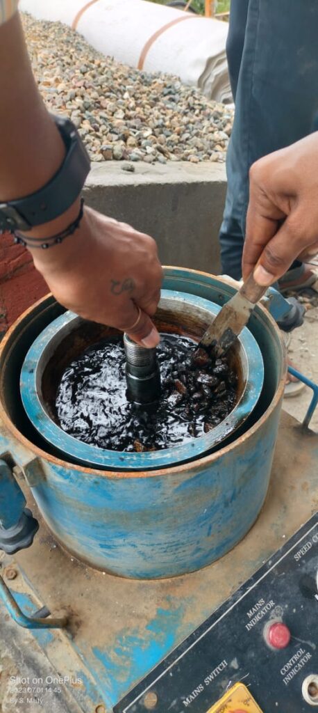
bitumen extraction

Bitumen Extraction Test – Objective, Procedure & Calculation

The Bitumen Extraction Test is a laboratory method used to determine the actual bitumen content present in a bituminous mix by separating the binder from aggregates using a suitable solvent. This test is essential for quality control, mix design verification, and compliance with MoRTH / IS:2720 (Part 2) and ASTM standards. Accurate bitumen content ensures proper pavement durability, strength, and resistance to deformation.

Bitumen Extraction Test – Objective, Procedure & Calculation Read More »

Bitumen, Bituminous Work

Embankment Construction Methodology | Highway Earthwork Guide

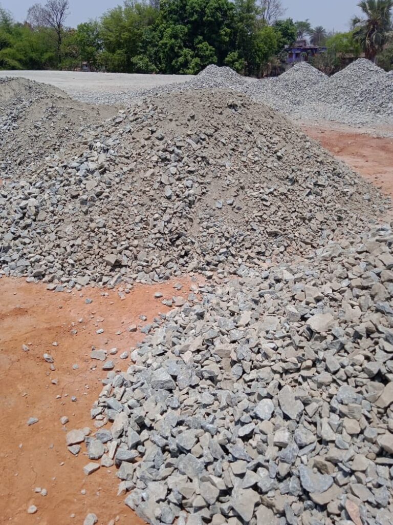
Embankment Construction Methodology with Quality Control | MoRTH Clause 305 Embankment Construction Methodology with Quality Control – MoRTH Clause 305 Scope of Work The work shall consist of construction of embankment with approved and specified materials obtained from approved borrow areas or suitable material obtained from roadway excavation and drain excavation and in accordance with clause 305 of MORTH specifications. Reference Standards MoRTH Specifications – Section 305 (5th Revision) IRC SP: 84 IS 2720 Series – Soil Testing Approved Project Drawings Manpower & Responsibilities Manpower & Responsibilities Construction Manager Engineer / Supervisor Land Surveyor Material Engineer Safety Supervisor Helpers Construction Manager He shall be overall responsible for the activity including: Planning and organizing resources required for execution in consultation with the Project Manager. Implementation of safety requirements during the work including utility services protection. Ensuring all relevant tests are conducted as per specification. Maintaining all QA/QC records as per contract requirements. Coordinating with the consultant engineer for obtaining necessary approvals for completed activities. Engineer / Supervisor Responsibilities include: Deployment of required resources at site as per planning. Execution of work as per approved drawings. Maintaining quality control as per specifications. Implementation of safety regulations at site. Obtaining approvals for completed works from consultant/authority. Land Surveyor Responsibilities include: Establishing reference points for alignment and levels. Ensuring correct setting out of works. Checking and recording levels of completed work. Coordinating with consultant staff for final approval of finished works. Material Engineer Responsibilities include: Implementation of quality procedures as per approved plan. Ensuring all materials meet specification requirements. Conducting required laboratory and field tests as per standards. Maintaining complete material testing records and reports. Safety Supervisor Responsibilities include: Ensuring safe execution of all site activities. Implementation of project safety plan and guidelines. Monitoring compliance of safety measures at site. Setting Out After completion of site clearance, the limits of embankment shall be marked by fixing pegs on both sides at regular intervals. The chainage boards and working bench mark shall be set outside the limits of construction areas. Material Selection & Borrow Area Testing Selection of Material and Borrow Areas Material The material used in embankment shall be soil, moorum, gravel, reclaimed material from pavement, fly ash, pond ash, a mixture of these or any other material approved by the AE. It shall be free of logs, stumps, roots, rubbish and any other material likely to deteriorate or affect the stability of the embankment. The material for embankment shall be obtained from the approved source with preference to the material becoming available from nearby roadway excavation or any other excavation under the contract. The material requirements shall be in accordance with Clause 305.2 of MORTH specifications. These materials shall be free from logs, stumps, roots, rubbish or any other ingredients likely to affect the stability of the embankment. The material that has LL less than 55%, PI less than 25%, and Free Swell Index less than 50% shall be used for embankment construction. The material which is having lab MDD 15.2 minimum as per IS: 2720 Part-8 shall be used in embankment filling. The sample from the borrow area shall be brought to the laboratory and tested for the above requirements. Clods and hard humps of earth will be broken to a maximum size of 75 mm for embankment. If the moisture content (NMC) is less than OMC, the water shall be added by sprinkling considering evaporation losses, so that at the time of compaction it is in the range of 1% above to 2% below the optimum moisture content. If NMC is more than OMC, the material can be allowed to dry by exposure to the sun. EMBANKMENT/STRUCTURE BACK FILLS The following type of material shall be considered un-suitable. Material from swamps, marshes and bogs. Peat, log, stump and perishable material. Soil classified as OL, OI, OH or Pt. in accordance with IS: 1498. Material susceptible to spontaneous combustion. Material in frozen condition. Clay having LL exceeding 70 and PI exceeding 45 for Embankment. Clay having LL exceeding 50 and PI exceeding 25 for Subgrade. Material with salts resulting in leaching in the embankment. Soils having free swelling index more than 50% shall not be used as filled material. Soil having acceptedbelow free swelling index (non-expensive soils) shall be used up to 500 mm below sub-grade/embankment top. Fill material having soluble Sulfate content exceeding 1.9 gm. of Sulfate per liter (As per BS: 1377 test 10) not to be deposited with 500 mm in contact with concrete structure or cement bound materials forming part of permanent work. Fill material having total Sulfate content exceeding 0.5% by mass. (Tested as per BS: 1377 test 9) shall not be deposited with 500 mm of metallic item forming part of Permanent Work. The maximum size of coarse material in earth mixture shall not exceed 75 mm for embankment fill and 50 mm for sub grade fill. Soil material shall satisfy density requirement as given in BELOW Density Requirements for Embankment & Subgrade Material Sl. No Type of Work Maximum Laboratory dry unit weight when tested as per IS: 2720 (Part 8) 1 Embankments up to 3.0 m high not subjected to extensive flooding. Not less than 15.2 KN/cum or 1.55 gm /cc. 2 Embankment exceeding 3.0 m ht. or Embankment of any height subject to long period of inundation. Not less than 16.0 KN/cum 1.631 gm/cc. or 1.6 gm/cc 3 Sub grade and earthen shoulder / backfill Not less than 17.5 KN/cum or 1.784 gm/cc Note: Materials used shall satisfy design CBR i.e. soaked CBR shall not be less than 12% and 10% as per design locations for Heavy weight fill material. This below is not applicable for light weight fill material. Compaction Requirement The Embankment /sub grade material shall be compacted in one or more layer as per contract. The compacted field density shall meet minimum density requirement as given in BELOW Compaction Requirements for Embankment & Sub grade Sl. No Type of work/material Relative Compaction % of max. Laboratories dry density as

Embankment Construction Methodology | Highway Earthwork Guide Read More »

Earthwork

Stone Matrix Asphalt (SMA)

Stone Matrix Asphalt (SMA) – Complete Technical Guide as per IRC & MoRTH Stone Matrix Asphalt (SMA) is a gap-graded bituminous mixture designed to provide exceptional rutting resistance, durability, and long-term pavement performance under heavy traffic loading. It consists of a stone-on-stone aggregate skeleton, rich bituminous mortar, mineral filler, and stabilizing fibres that work together to create a highly stable and durable pavement surface. Originally developed in Germany, SMA has become one of the most preferred surfacing materials for national highways, expressways, urban arterial roads, intersections, climbing lanes, and other heavily trafficked pavements. In India, the requirements for SMA are specified under MoRTH Clause 515, which covers materials, mix design, production, laying, compaction, and quality control requirements. This comprehensive guide explains the composition, design philosophy, material requirements, construction methodology, special performance tests, and quality control procedures for Stone Matrix Asphalt in accordance with IRC and MoRTH specifications. MoRTH Clause 515.1 – Scope of Stone Matrix Asphalt (SMA) This clause covers the construction of fibre-stabilized Stone Matrix Asphalt (SMA) in single or multiple layers over a previously prepared bituminous bound surface. SMA may be used as either a wearing course or a binder/intermediate course depending upon the aggregate gradation and layer thickness requirements. Application of SMA Layers The SMA mixture consists of a gap-graded aggregate skeleton, rich bituminous mortar, mineral filler, and stabilizing fibres. The fibres help prevent binder drain down and ensure uniform distribution of the higher bitumen content characteristic of SMA mixes. SMA Type Maximum Aggregate Size Recommended Use Nominal Layer Thickness 13 mm SMA 13.2 mm Wearing Course 40–50 mm 19 mm SMA 19 mm Binder / Intermediate Course 45–75 mm Engineering Significance 13 mm SMA is primarily used as a wearing course due to its superior surface texture, skid resistance, and riding quality. 19 mm SMA is generally used as a binder or intermediate course where higher structural capacity and load distribution are required. The specified layer thickness ensures adequate aggregate interlock, proper compaction, and development of the stone-on-stone contact structure essential for SMA performance. SMA is particularly suitable for highways, expressways, intersections, climbing lanes, toll plazas, and other locations subjected to heavy traffic loading and rutting stresses. Practical Site Note Before laying SMA, the underlying bituminous layer should be structurally sound, properly compacted, clean, and provided with an approved tack coat to ensure adequate bond between layers. Site Engineer’s Checklist: Use 13 mm SMA for wearing course (40–50 mm thick). Use 19 mm SMA for binder/intermediate course (45–75 mm thick). Ensure fibre addition at the approved dosage. Verify layer thickness before compaction. Maintain paving and rolling temperatures as per JMF. Material Requirements for Stone Matrix Asphalt (SMA) The performance of Stone Matrix Asphalt (SMA) depends significantly on the quality of constituent materials. MoRTH Clause 515.2 specifies stringent requirements for bitumen, aggregates, mineral filler, and stabilizing additives to ensure the development of a durable stone-on-stone aggregate skeleton capable of resisting rutting and moisture damage under heavy traffic loading. 1. Bitumen The binder used in fibre-stabilized SMA shall be viscosity grade paving bitumen conforming to IS:73 or Modified Bitumen conforming to IS:15462 and IRC:SP:53. The selected binder grade shall be capable of satisfying all mix design requirements and shall conform to the requirements specified in MoRTH Table 500-2. Engineering Significance: SMA typically contains higher binder content than conventional Bituminous Concrete. Therefore, selection of an appropriate binder grade is critical for achieving durability, rut resistance, and resistance to binder drain down. 2. Coarse Aggregate Coarse aggregates shall consist of crushed rock retained on the 2.36 mm sieve. Aggregates shall be clean, hard, durable, cubical in shape, and free from dust, clay, organic matter, and other deleterious substances. Physical Requirements of Coarse Aggregates Property Test Method Requirement Cleanliness IS:2386 Part 1 < 2% passing 0.075 mm sieve Combined Flakiness & Elongation Index IS:2386 Part 1 < 30% Los Angeles Abrasion Value IS:2386 Part 4 < 25% Aggregate Impact Value IS:2386 Part 4 < 18% Polished Stone Value* IS:2386 Part 114 > 55% Soundness (Na₂SO₄) IS:2386 Part 5 < 12% Water Absorption IS:2386 Part 3 < 2% *Polished Stone Value requirement is not applicable for SMA used as binder/intermediate course. Engineering Significance: SMA derives its load carrying capacity primarily from stone-on-stone aggregate contact. Therefore, aggregate strength, durability, and shape requirements are more stringent than conventional dense graded mixes. 3. Fine Aggregate Fine aggregate passing the 2.36 mm sieve and retained on the 0.075 mm sieve shall consist entirely of crushed manufactured sand obtained from approved crushing operations. 100% crushed material Clean and durable particles Non-plastic in nature Free from organic and deleterious matter Sand Equivalent Value ≥ 50 Engineering Significance: Manufactured sand improves internal friction and stability of SMA compared to natural river sand. 4. Mineral Filler Mineral filler shall consist of finely divided mineral matter such as stone dust or hydrated lime. Use of fly ash as filler is not permitted. Grading Requirements of Mineral Filler IS Sieve Cumulative Passing (%) 0.600 mm 100 0.300 mm 95–100 0.075 mm 85–100 The Plasticity Index of filler shall not exceed 4. This requirement does not apply when hydrated lime is used. Special Requirement: If the SMA mixture fails the Moisture Susceptibility Test (AASHTO T 283), a minimum of 2% hydrated lime by total aggregate weight shall be incorporated. 5. Stabilizing Additive (Cellulose Fibre) Only pelletized cellulose fibres shall be used as stabilizing additives in SMA. The fibres prevent binder drain down and ensure uniform distribution of the rich bituminous mortar. Minimum Dosage 0.3% by weight of total mix (on loose fibre basis) Performance Requirement The fibre dosage shall be sufficient to ensure that binder drain down does not exceed 0.3% when tested in accordance with ASTM D6390. Cellulose Fibre Requirements Property Requirement Maximum Fibre Length 8 mm Ash Content Maximum 20% Oil Absorption More than 4 times fibre weight Moisture Content Less than 5% Site Engineer’s Check: Verify manufacturer’s certificate for fibre properties and ensure fibres are protected from moisture before use. SMA Mix Design Requirements After selection of suitable materials

Stone Matrix Asphalt (SMA) Read More »

Uncategorized

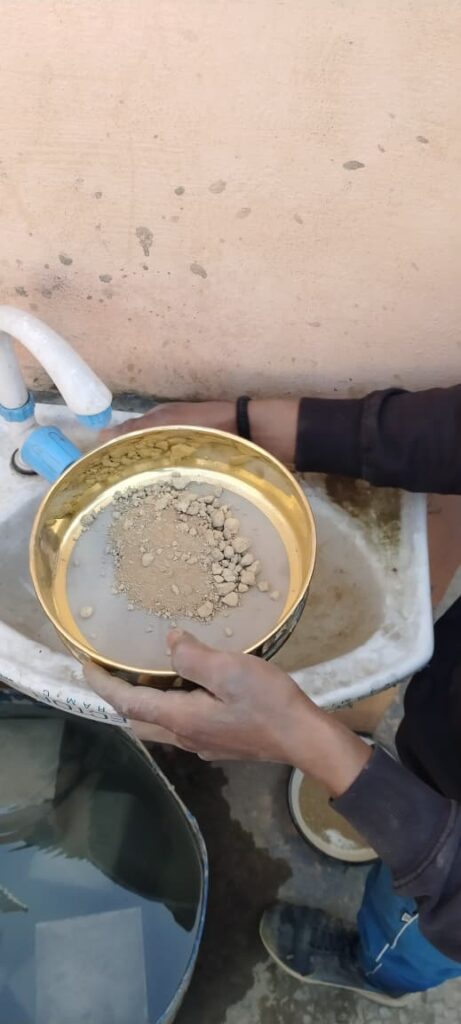
Grain Size Analysis (Sieve Analysis) of Soil – Procedure, Calculations & Results

Grain Size Analysis of Soil – Sieve Analysis Procedure, Calculation & Interpretation Author: Kishor Kumar · Updated: February 2026 · Read time: ~15 minutes 1. Introduction The Grain Size Analysis of Soil, commonly known as the Sieve Analysis, is a fundamental laboratory test used to determine the particle size distribution of soil. It plays a crucial role in highway and civil engineering projects. Soil Identification and Classification Most of the methods for soil identification and classification are based on certain physical properties of the soils. The commonly used properties for the classification are the grain size distribution, liquid limit and plasticity index. These properties have also been used in empirical design methods for flexible pavements, and in deciding the suitability of sub grade soils. Grain size analysis also known as mechanical analysis of soils is the determination of the percent of individual grain sizes present in the sample. The mechanical Analysis consists of two parts: Determination of coarse material using sieves. Analysis of fine grained fraction by sedimentation method. The sieve analysis is a simple test consisting of sieving a measured quantity of material through successively smaller sieves. The weight retained on each sieve is expressed as a percentage of the total sample. The sedimentation principle has been used for finding the grain size distribution of fine soil fraction; two methods are commonly used: Pipette method Hydrometer method The grain size distribution of soil particles of size greater than 75 micron is determined by sieving the soil on a set of sieves of decreasing sieve opening placed one below the other and separating out the different size ranges. Two methods of sieve analysis are as follows: Wet sieving applicable to all soils Dry sieving applicable only to soils, which have negligible proportion of clay and silt The soil received from the field is divided into two parts: one, the fraction retained on 2mm sieve and the other passing 2mm sieve. The sieve analysis also may be carried out separately for these two fractions. The fraction retained on 2mm sieve may be subjected to dry sieving using bigger sieves and that passing 2mm sieve may be subjected to wet sieving; however if this fraction consists of single grained soil with negligible fines passing 0.075mm size, dry sieving may be carried out. Proper soil gradation ensures good drainage, uniform compaction, and strong load-bearing capacity. Coarse-grained soils are generally suitable for sub-base layers, while fine-grained soils may require stabilization. 2. Purpose of Grain Size Analysis Determine particle size distribution and gradation Assist in soil classification (Gravel, Sand, Silt, Clay) Design subgrade, embankment, and pavement layers Assess permeability and drainage characteristics Guide soil stabilization decisions 3. Applicable Standards IS 2720 (Part 4) – Grain Size Analysis IS 2720 (Part 1) – Sample Preparation MoRTH Specifications – Subgrade, GSB & WMM ASTM D6913 / D422 – International standards 4. Apparatus Required Standard sieve set (4.75 mm to 75 μm) Mechanical sieve shaker Weighing balance (0.1 g accuracy) Oven (105°C to 110°C) Hydrometer (for fine soils) Brush, spatula, containers 5. Sample Preparation The soil sample should be oven-dried at 105°C–110°C and cleaned of organic matter. Lumps should be broken gently without crushing particles. Take ~500 g dry soil sample Ensure moisture content is minimal Remove oversized particles and debris Mix thoroughly for uniformity 6. Test Procedure – Sieve Analysis Sieve Analysis – Coarse Fraction (a) Fraction retained on 2.0mm sieve: Sufficient quantity of the dry soil retained on 2.0mm sieve is weighed out. The quantity of sample taken may be increased when the maximum size of particles is higher. The sample is separated into various fractions by sieving through the set of sieves of sizes 100 mm, 63 mm, 20 mm, 6 mm, 4.75 mm and 2 mm IS sieves. Additional sieve sizes may also be introduced if necessary. After initial sieving, the material retained on each sieve is collected, the lumps are broken down using mortar and rubber covered pestle and is re-sieved. Thus, the soil fraction retained on each sieve is carefully collected and weighed. Sieve Analysis – Fine Fraction (b) For the fraction passing 2.0mm sieve and retained on 0.075mm sieve: Dry sieving may be done in the case of soils which are cohesion less, single grained and without lumps. Rifling or quartering method takes the required quantity of soil sample, dried in oven at 1050 to 1100°C and is subjected to dry sieve analysis using a set of sieves with sieve openings 2.0 mm, 0.6 mm, 0.425 mm, 0.15 mm and 0.075 mm, pan and lid. Additional sieves may be used or any of the sieves removed, depending upon the requirement of the test. The material retained on each sieve and on the pan are separately collected and weighed. Wet sieving may be adopted in the case of clayey or cohesive soils. Required quantity of sample taken by riffling is weighed. The sample is spread in a tray or bucket and covered with water. In case of soils having fractions that are likely to flocculate, a dispersing agent like sodium hexametaphosphate (2.0g) or sodium hydroxide (1.0g) and sodium carbonate (1.0g) per liter of water may be added to the water. The mix is stirred and left for soaking. The soaked soil specimen is placed over the set of sieves with the finest sieve and pan at the bottom and washed thoroughly. Washing is continued till the water passing each sieve is substantially clean. The fraction of each sieve is emptied carefully without loss of material in separate trays, oven dried at 1050 to 1100°C and each fraction weighed separately. Calculations – Sieve Analysis CALCULATIONS: The weight of dry soil fractions retained on each sieve is calculated as a percentage of the total dry weight of the sample taken. Results – Grain Size Analysis RESULTS: The results are plotted on a semi-logarithmic graph with the grain size or sieve size on the X-axis (log scale) and the percentage finer of each sieve on the Y-axis (ordinary scale). The smooth curve joining the

Grain Size Analysis (Sieve Analysis) of Soil – Procedure, Calculations & Results Read More »

Soil

© 2026 HIGHWAY QUALITY TEST. All rights reserved.

WhatsAppNeed Help?
Scroll to Top