HIGHWAY QUALITY TEST

Precision Testing. Proven Quality. Safer Infrastructure.

Stripping Value of Aggregate – Complete Guide for Highway Construction

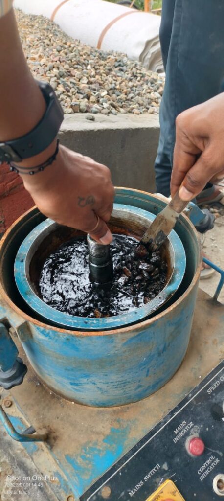
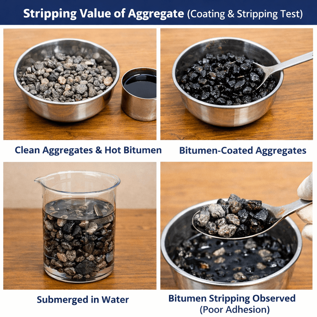
Stripping Value Test of Aggregate – Purpose, Importance, Applications & Apparatus By Kishor Kumar | Highway Quality Test Updated: February 2026 • Read Time: 8 Minutes The Stripping Value Test of Aggregate evaluates the ability of bitumen to remain firmly adhered to the surface of coarse aggregates when exposed to water. From a contractor’s perspective, this test is one of the most important quality control checks before approving aggregates for bituminous works because poor adhesion between bitumen and aggregate is a major cause of premature pavement failures. As a Material Engineer on highway projects, I always recommend conducting the stripping value test before large-scale production of Dense Bituminous Macadam (DBM), Bituminous Concrete (BC), and other hot mix asphalt layers. The test helps identify whether the selected aggregate source is suitable or whether an anti-stripping additive will be required to achieve durable pavement performance. 1. What is the Stripping Value Test? The Stripping Value Test determines the percentage of aggregate surface from which the bitumen film gets detached after immersion in hot water under specified laboratory conditions. The higher the stripping value, the poorer the bond between aggregate and bitumen, increasing the likelihood of moisture damage and pavement deterioration. The test primarily evaluates: Adhesion between bitumen and aggregate. Resistance of coated aggregates to moisture attack. Suitability of aggregate for bituminous pavement construction. Need for anti-stripping agents or alternative aggregate sources. 2. Engineering Significance Water is one of the biggest enemies of flexible pavements. Once moisture penetrates the pavement structure, it weakens the adhesive bond between bitumen and aggregate. This process, known as stripping, causes gradual separation of the binder from the aggregate surface. From practical highway construction experience, aggregates exhibiting high stripping values often lead to: Ravelling of the pavement surface. Premature pothole formation. Loss of aggregate from the wearing course. Reduced fatigue life of asphalt layers. Higher maintenance costs during the concession period. Selecting aggregates with good stripping resistance significantly improves the durability and service life of bituminous pavements. 3. Importance of the Stripping Value Test The Stripping Value Test is an essential quality control test for highway construction because it verifies whether aggregates can maintain a durable bond with bitumen under wet service conditions. Evaluates moisture susceptibility of aggregates. Ensures proper adhesion between bitumen and aggregate. Helps comply with MoRTH and project specifications. Reduces the risk of early pavement failures. Assists in selecting suitable aggregate sources. Determines the requirement of anti-stripping additives. Improves long-term pavement durability. Engineering Note: Lower stripping values indicate better adhesion between bitumen and aggregate, resulting in improved resistance to moisture damage and longer pavement service life. 4. Applications in Highway Construction The Stripping Value Test is routinely carried out during material approval and mix design stages of highway projects. Contractor laboratories perform this test before approving aggregates for bituminous works. Typical applications include: Approval of aggregate quarries for asphalt works. Selection of coarse aggregates for Bituminous Concrete (BC). Quality control of Dense Bituminous Macadam (DBM). Evaluation of aggregates used in Bituminous Macadam (BM). Assessment of aggregate compatibility with different penetration grade bitumen. Verification of aggregate quality during source changes. Determining the necessity of anti-stripping additives. The test is widely specified for National Highways, State Highways, Expressways, PMGSY roads, EPC projects, HAM projects, and other flexible pavement works where long-term moisture resistance is critical. 5. Applicable Standards IS 6241 – Method for Determination of Stripping Value of Road Aggregates. MoRTH Specifications – Requirements for Bituminous Layers. IRC:SP:62 – Guidelines for Design and Construction of Bituminous Pavements. 6. Apparatus Required The following equipment is required to perform the Stripping Value Test: Clean coarse aggregate sample. Bitumen of the specified penetration grade. Water bath maintained at 60 ± 1°C. Glass beakers or suitable containers. Oven for drying aggregates. Electronic weighing balance. Sieves for sample preparation. Mixing tray and spatula. Thermometer. Tongs and laboratory accessories. Contractor’s Practical Tip: Before approving any new aggregate source for DBM or BC production, always perform the Stripping Value Test. If excessive stripping is observed, use an approved anti-stripping agent or consider changing the aggregate source. Addressing adhesion issues during material selection is far more economical than repairing moisture-induced pavement failures after construction. 7. Test Procedure The Stripping Value Test should be carried out carefully under controlled laboratory conditions to obtain reliable and repeatable results. From a contractor’s QA/QC perspective, maintaining the correct temperature and ensuring uniform coating of aggregates are the most critical aspects of this test. Wash and oven-dry the aggregate sample to remove dust, moisture, and other contaminants. Heat the bitumen to the specified temperature until it becomes sufficiently fluid for proper coating. Coat the aggregate particles uniformly with bitumen so that every exposed surface is completely covered. Allow the coated aggregates to cool slightly before placing them in a clean glass container. Immerse the coated aggregates in a water bath maintained at 60 ± 1°C for 24 hours. After immersion, carefully remove the aggregates without disturbing the remaining bitumen coating. Dry the aggregates in an oven at approximately 105°C until a constant weight is achieved. Inspect the aggregate surface visually and record the amount of bitumen stripped from the aggregate surface. Measure the required weights and calculate the stripping value. Practical Site Tip: Always use clean, dust-free aggregates. Even a thin layer of dust can significantly reduce bitumen adhesion and produce misleading stripping results. 8. Stripping Value Calculation The stripping value is expressed as the percentage loss of bitumen coating from the aggregate surface after immersion in water. Stripping Value (%) = ((W1 − W2) / W1) × 100 Where: W1 = Initial weight of coated aggregate (g) W2 = Final weight after immersion and drying (g) Initial Weight (W₁) Final Weight (W₂) Stripping Value (%) 500 g 460 g 8% 500 g 450 g 10% A lower stripping value indicates stronger adhesion between bitumen and aggregate, resulting in better resistance against moisture-induced pavement damage. 9. Result Interpretation The following table provides a general guideline for interpreting stripping value results during material approval. Stripping Value (%) Aggregate Adhesion Quality

Stripping Value of Aggregate – Complete Guide for Highway Construction Read More »

Aggregate
pqc

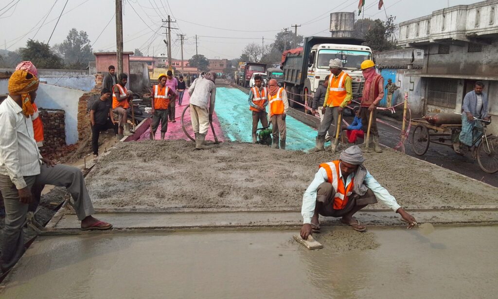
PQC M40 Construction, QA/QC, Failures & Maintenance | Highway Engineering Guide PQC M40 Construction, QA/QC, Failures & Maintenance Guide 1. Overview of PQC Pavement Quality Concrete (PQC) is a rigid pavement layer designed to directly transfer traffic loads to the subgrade through slab action. It is widely used in National Highways for long service life (30–40 years). ✔ Key Advantage: High flexural strength, rut-free surface, excellent durability, and low maintenance requirement. 2. Step-by-Step PQC Construction Process 2.1 Subgrade & GSB Preparation The quality of Pavement Quality Concrete (PQC) primarily depends on the strength and uniformity of the foundation layers. Before laying Dry Lean Concrete (DLC), the completed subgrade and Granular Sub Base (GSB) shall be prepared, inspected, and approved to ensure adequate load-bearing capacity, proper drainage, and accurate pavement geometry. Setting Out: Establish centre line, edge lines, benchmarks, offsets, and finished levels using Total Station/Auto Level before commencing earthwork. Subgrade Preparation: Trim the prepared subgrade to the required line, level, camber, and cross fall. Remove loose soil, organic matter, soft pockets, and any unsuitable material encountered during trimming. Compaction: Compact the subgrade uniformly using suitable vibratory rollers until the specified density (minimum 97% of Maximum Dry Density as per project specifications) is achieved. Moisture content shall be maintained close to Optimum Moisture Content (OMC). Proof Rolling: Carry out proof rolling using a loaded dump truck or pneumatic tyred roller to identify weak, yielding, or pumping areas. Excavate and replace defective portions with approved material before proceeding. Drainage Arrangement: Ensure side drains and temporary drainage channels are functional so that no water stagnation occurs on the prepared subgrade during construction. GSB Laying: Spread Granular Sub Base (GSB) material in the specified layer thickness using a motor grader or sensor paver. Control segregation during unloading and maintain uniform thickness throughout the carriageway. GSB Compaction: Compact each GSB layer with vibratory rollers until the specified field density is achieved. Add water uniformly wherever required to maintain optimum moisture for effective compaction. Surface Finish: After compaction, the GSB surface shall be firm, dense, and free from ruts, loose aggregates, depressions, or segregated patches. Any irregularities shall be corrected before laying the next layer. Quality Control: Verify field density, moisture content, layer thickness, levels, cross fall, and longitudinal profile at the prescribed frequency. The completed GSB shall satisfy all tolerance limits before commencement of DLC. Final Approval: Clean the finished GSB surface thoroughly and obtain Engineer’s approval before laying Dry Lean Concrete (DLC). Traffic movement over the approved surface should be restricted to prevent damage or contamination. 2.2 Dry Lean Concrete (DLC) Layer Preparation Dry Lean Concrete (DLC) is the rigid foundation layer placed below Pavement Quality Concrete (PQC). It provides a stable, uniform, and non-erodible platform for PQC, distributes wheel loads to the sub-base, minimizes pumping, and facilitates the movement of paving equipment during concrete pavement construction. Surface Preparation: Before laying DLC, ensure the approved GSB surface is clean, compact, free from loose material, and maintained at the specified line, level, thickness, and cross fall. Any damaged or segregated portions shall be repaired. Mix Production: Produce DLC using a calibrated batching plant in accordance with the approved mix design. Control water content carefully to achieve the specified consistency without segregation. Transportation: Transport the concrete in transit mixers or dumpers without delay. Prevent contamination, excessive moisture loss, and segregation during transportation. Mechanical Laying: Spread the DLC uniformly using a sensor paver or mechanical paver to the specified thickness. Manual laying should be limited only to inaccessible or minor areas. Compaction & Finishing: Compact the laid concrete immediately using internal and surface vibrators integrated with the paver. Finish the surface with a screed to achieve the required level and smoothness without overworking the concrete. Level & Thickness Control: Continuously check layer thickness, longitudinal profile, cross fall, and surface levels during paving. Any deficiency beyond permissible tolerances shall be rectified immediately. Joint Construction: Construct longitudinal and transverse construction joints at planned locations. The edges of completed panels shall be neat, straight, and properly protected before adjacent concreting. Curing: Begin curing immediately after the surface has hardened sufficiently. Cure the DLC continuously for a minimum of 7 days using water or approved curing methods to prevent rapid moisture loss and shrinkage cracking. Quality Control: Verify thickness, density, compressive strength, line, level, and surface regularity at the prescribed frequency. Only approved DLC shall be accepted for subsequent PQC paving. Pre-PQC Inspection: Before laying PQC, inspect the DLC surface for cracks, honeycombing, loose particles, laitance, contamination, and ponding water. Clean the surface thoroughly and obtain Engineer’s approval prior to commencement of PQC. Site Engineering Tip: DLC acts as the structural foundation of rigid pavement. Poor compaction, inadequate curing, low thickness, or an uneven surface can lead to pumping, loss of support, slab cracking, faulting at joints, and premature failure of the PQC pavement. Investing time in proper DLC construction significantly improves the long-term performance and service life of the concrete pavement. 2.3 Separation Membrane A separation membrane is a polyethylene sheet laid over the finished DLC surface before placing Pavement Quality Concrete (PQC). It acts as a bond breaker between DLC and PQC, allowing the concrete slab to expand and contract freely due to temperature and moisture variations. Proper installation of the membrane minimizes frictional restraint, reduces shrinkage stresses, and improves the long-term performance of the rigid pavement. Surface Preparation: Before laying the membrane, ensure the DLC surface is clean, dry, smooth, and free from loose particles, laitance, sharp aggregates, oil, or standing water. Repair any damaged or uneven areas. Material: Use approved polyethylene (PE) sheet of 125–200 micron thickness (or as specified in the contract). The sheet shall be free from tears, punctures, folds, and manufacturing defects. Laying Procedure: Unroll the membrane carefully over the DLC surface without wrinkles or air pockets. Lay it continuously in the direction of paving and ensure complete coverage of the pavement width. Overlap: Provide a minimum 300 mm overlap between adjacent sheets. The overlaps shall remain flat and shall not create ridges

pqc Read More »

Uncategorized

PQC Methodology

Pavement Quality Concrete (PQC) M40 – Complete Construction & QA/QC Guide Pavement Quality Concrete (PQC) M40: Complete Construction & QA/QC Guide 1. General Overview Pavement Quality Concrete (PQC) is the final structural layer of rigid pavement designed to directly carry traffic loads and distribute them safely to underlying layers. It is a high-strength cement concrete layer constructed over DLC/WMM/GSB as per approved drawings and MoRTH specifications. The success of PQC depends on strict control of: Sub-base readiness (DLC/WMM quality) Concrete mix design and production control Continuous paving without interruption Proper vibration, finishing, and leveling Joint construction and curing discipline Applicable Standards Reference Documents S. No. Document Description 1 Contract Agreement 2 IRC: SP: 84-2014 3 Ministry of Road Transport & Highways Specifications (MoRTH – 5th Revision) 4 Relevant Drawings 2. Pre-Construction Requirements Pavement Quality Concrete (PQC) shall be executed only after ensuring that all pre-construction conditions are satisfied as per MoRTH and approved project specifications. 2.1 Base Layer Approval (DLC / GSB) PQC shall not be laid until the underlying layer is fully approved by the Engineer. Formation / DLC / GSB must be properly compacted Surface shall be true to line, level, and cross fall Free from loose soil, dust, and contamination Field Density Test (FDT) results must be approved Surface shall be thoroughly cleaned before PQC laying Strong Base = Long Life Pavement. Any weakness in DLC/GSB directly affects PQC performance. 2.2 Plant & Equipment Approval The following equipment must be deployed, tested, and approved before PQC execution: Fully calibrated concrete batching plant Transit mixers / dumpers in adequate quantity Needle vibrators (minimum 2 per paving team) Screed vibrator / slip form paving machine (sensor paver preferred) Water tanker for curing operations 3 m straight edge and leveling instruments Concrete saw cutting machine for joint cutting 3. Survey, Setting Out & String Line Control Accurate survey control is essential for achieving correct alignment, level, and riding quality of PQC pavement. 3.1 Control Points Center line established using Total Station Edge lines marked as per approved drawings Formation levels transferred from GFC drawings Benchmarks shall be protected throughout construction 3.2 Level Control System String line system used for fixed form paving Automatic sensor control system used for slip form paving Level pegs installed at specified intervals 👉 Even a small level deviation at this stage directly affects pavement smoothness and riding quality. 4. Concrete Mix Design & Production 4.1 Mix Design Requirements Concrete mix shall be designed as per approved design mix (generally M40/M35 or as specified in contract). Design as per IS 10262 and MoRTH Clause 602 Minimum cement content as per specification requirements Strict control of water-cement ratio Use of approved admixtures for workability and setting control 4.2 Batching Plant Operations Batching plant shall be fully calibrated before start of work Moisture correction in aggregates is mandatory daily Weigh batching system only (volume batching strictly prohibited) Uniform mixing time shall be maintained for every batch Mix consistency shall be checked regularly Consistent batching = Consistent strength. Any variation in batching directly affects flexural strength of PQC. 5. Transportation of Concrete Concrete shall be transported using transit mixers only Segregation of concrete during transport shall be strictly avoided No delay beyond initial setting time is permitted Concrete shall be discharged immediately at site Site Slump Control Slump shall be checked at site for every batch Typical range: 30 – 60 mm (as per design requirement) No water shall be added at site without Engineer approval Any delay or re-tempering of concrete at site will lead to rejection of the batch. 6. Laying of PQC (Execution Control: From QA/QC point of view, PQC laying is not just a construction activity but a controlled engineering process where time, vibration, placement, and finishing directly govern the structural performance and service life of the pavement. Strict supervision, continuous monitoring, and zero-tolerance control are required during this stage. 6.1 Placement Control : Concrete placement shall be executed in a continuous and uninterrupted operation to ensure structural integrity of PQC slabs. Placement shall be continuous without stoppage under normal conditions Cold joints are strictly prohibited in PQC construction Concrete shall not be rehandled, remixed, or re-tempered at site Concrete shall be discharged ahead of the paving machine in a controlled and uniform manner From QA/QC perspective: Any interruption in placement leads to weak planes, reduced load transfer efficiency, and early pavement distress. 6.2 Compaction Control (Critical QA/QC Activity) Compaction is the most sensitive operation in PQC construction and must be strictly monitored by QA/QC engineers during execution. Internal needle vibrators shall be used uniformly across the full slab width Vibration pattern shall follow systematic overlapping to avoid un-compacted zones Vibrators shall be inserted vertically and withdrawn slowly to ensure full densification Over-vibration must be strictly avoided to prevent segregation and bleeding of cement slurry 👉 QA/QC Insight: Proper compaction ensures homogeneous density, high flexural strength, and long-term pavement durability. Improper vibration is a primary cause of honeycombing and premature failures. 6.3 Finishing Control (Surface Quality Requirement) Finishing operations directly define the riding quality, skid resistance, and service performance of the pavement and therefore require strict QA/QC supervision. Screeding shall be carried out immediately after completion of compaction Surface shall be finished to required line, level, and cross fall as per drawings Floating shall be done to achieve uniform surface texture and smoothness Edge correction shall be carried out manually wherever required with full control From HOP perspective: Final finishing determines client acceptance. Even minor surface irregularities can lead to rejection or grinding requirement. 7. Surface Texturing Surface texturing in Pavement Quality Concrete (PQC) is a critical finishing operation carried out to ensure adequate skid resistance, safe vehicular movement, and long-term riding performance of the pavement surface. From a QA/QC and Head of Project perspective, texturing is directly linked with road safety, surface performance, and client acceptance. 7.1 Purpose of Surface Texturing To provide adequate skid resistance for moving traffic To improve braking performance and safety under wet conditions To ensure uniform surface roughness

PQC Methodology Read More »

Concrete Work
BC laying work

Bituminous Concrete

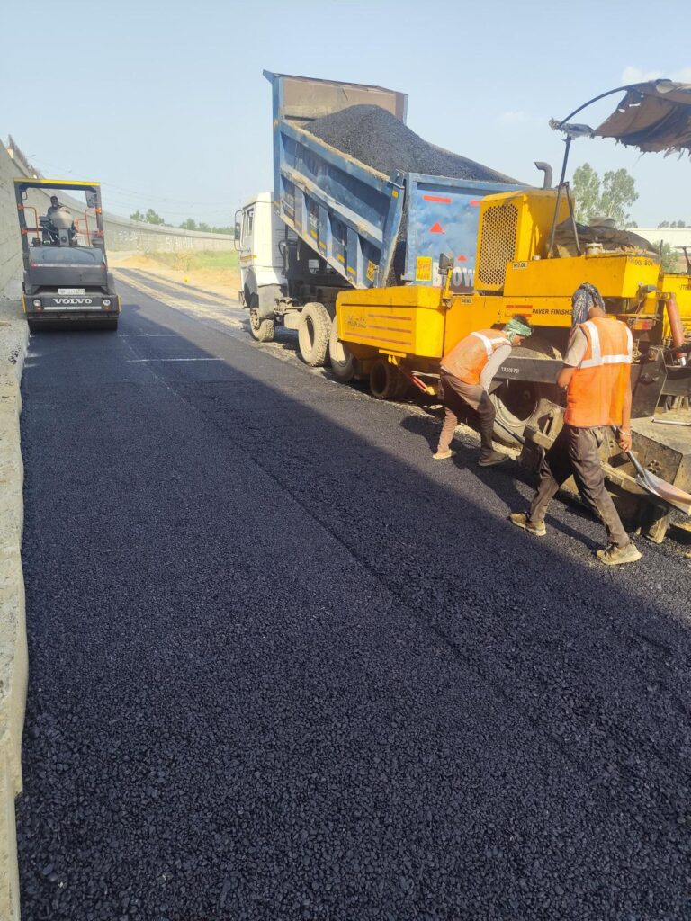
Top 9 Proven Steps for Bituminous Concrete (BC) | MoRTH Clause 507 Top 9 Proven Steps for Bituminous Concrete (BC) Construction Quick Summary: Bituminous Concrete (BC) is the final wearing course of flexible pavement laid in 30–50 mm thickness over DBM or bituminous base. Construction shall strictly follow MoRTH Clause 507, including approved mix design, controlled laying temperature, proper compaction and quality control tests. 1. Scope Methodology for laying of DBM in this project is detailed herein under. This method statement is based on parameters conforming to MoRTH, MS-2 Specifications. The construction of pavement layers on existing road involves the dismantling of existing bituminous layers, widening and strengthening of the existing road. This work covers preparation of surface, tack coat application, production of BC mix, transportation, laying, compaction, joint treatment and quality control testing in accordance with MoRTH Clause 507. 2. Reference Standards MoRTH Specifications – Clause 507 (5th Revision) IRC: SP: 84 – Manual of Specifications IS: 73 & IS: 15462 – Bitumen Standards IS: 2386 (All Parts) – Aggregate Testing Standards ASTM / AASHTO and MS-2 7th Rev– Marshall Mix Design Top Level Sheet – DBM (Dense Bituminous Macadam): Approved Mix Design & Approved GFC Drawings 3. Equipment Required Hot Mix Plant with automatic controls Self-propelled sensor paver with electronic, tamping/vibrating extendible screed (as per Clause 501.5) Tandem vibratory rollers Pneumatic Tyred Roller (PTR), 12–15 tonnes with minimum tyre pressure of 5.6 kg/cm² Bitumen pressure distributor/sprayer with accessories (as per Clause 502.4.1) Mechanical broom and air compressor for surface cleaning Core cutting machine for density testing Sufficient number of tippers for continuous and uninterrupted laying Materials & Job Mix Design Test Procedure of DBM & BC Mix Design (as per MoRTH & IRC Specifications) 1: Raise RFI for sampling of aggregates for DBM/BC mix design. 2: Sample the cold bin individual aggregates jointly. 3: Conduct individual gradation for aggregate as mentioned in MoRTH 500-10. 4: Blend the aggregate to meet the specified limits as mentioned in MoRTH 500-10. 5: Conduct the tests for aggregate to confirm its suitability for asphalt mix works: 6: AIV or LAAV, FI & EI, Stripping value, Water Absorption, Sand Equivalent value test to meet its suitability for DBM & BC as mentioned in MoRTH. 7: Feed the cold bin blending aggregate proportion in the Hot Mix Plant & take the individual hot bin aggregates. 8: Conduct specific gravity & water absorption test in the hot bin aggregates. Sl. No. 9: Conduct the individual gradation for aggregate & blend the aggregate to achieve the limit specified in MoRTH Table 500-10. 10: Feed the obtained blending proportion in the Hot Mix Plant and take the combined mix sample and check the combined gradation tests as mentioned in MoRTH 500-10. 11: Conduct the following tests for bitumen: Softening Point Test, Penetration Test, Viscosity Test from the approved bitumen source. 12: Prepare the mix with different binder content & find the Maximum Specific Gravity of the mix as per ASTM D-2041. 13: Cast the Marshall moulds with different binder content to check VMA, VFB, GSA, Air Voids, Stability & Flow of the mix. 14: With the obtained result plot the graph for Bulk Density, Marshall Stability, Air Voids, Flow, VMA & VFB. 15: All test data are interpreted & marked at which % all criteria passes. 16: Optimum Binder Content (OBC) has been found from chart. 17: Retained Stability Test conducted at OBC. 18: Refusal Density of the BC mix to be checked at 75, 150, 300 blows. 19: Marshall Quotient found for BC as per Table 7 of IRC SP:53-2002. 20: Confirmatory moulds casted & tested for Stability, Flow, VFB, VMA. Bituminous material of VG-40 grade shall confirm to the specifications of IS-73(2013). If modified binder is used then CRMB / PMB conforming to the requirement of CL.501.2.1, 507.2.1, IRC-SP-53-2010 and IS 15462-2004. Approved Aggregate and filler shall confirm two of MoRTH Cl.501.2 & Cl.507.2. Job Mix Formula (JMF): The Job Mix Formula (JMF) for Bituminous Concrete (BC) shall be developed and approved for use in the works in the presence of the Authority Engineer. The JMF shall include the following details: Source and location of all materials (bitumen, coarse aggregate, fine aggregate, and filler) Proportions of all constituent materials Binder type and percentage by weight of total mixture Coarse aggregate, fine aggregate, and mineral filler percentage Combined grading with specified sieve passing limits as per BC requirements Marshall test results as per Table 500-11 (Stability, Flow, Density, Air Voids, VMA, VFB) Aggregate compliance with MoRTH Clause 501.2 & Clause 507.2 Mixing, laying, and compaction temperature ranges Optimum Bitumen Content (OBC) and volumetric properties of mix Job Mix Design for BC shall be conducted in the Field Laboratory using Marshall Method. The materials shall be collected directly from the stockyard / storage tank and shall be checked for various physical requirements. The testing shall be carried out in the presence of the Consultant and submitted for approval. Approval of JMF: Approval shall be based on witnessed testing by the Independent Engineer. Samples shall be tested in in-house QC lab. Any change in material source requires submission of new JMF for approval prior to execution. Plant Trials: After laboratory approval, plant trials shall be conducted to ensure uniform mix production. Permissible variations shall comply with Table 500-13 limits. Laying Trials: Once the plant trials have been successfully completed and approved, the laying trials are executed to demonstrate that the proposed mix can be successfully laid and compacted in accordance with Clause 501. The laying trial shall be carried out on a suitable area which is not to form part of the works. The area of the laying trials shall be a minimum of 100 sq. m. of construction similar to that of the project road, and it shall be in all respects, particularly compaction, the same as the project construction, on which the bituminous material is to be laid. Information to AE is given of the proposed method for laying and compacting the material. The density

Bituminous Concrete Read More »

Bituminous Work

What is Bitumen? Grade, Types, Properties

Bitumen is a viscous, black, sticky, and highly cementitious substance derived from crude petroleum through a refining process. It is primarily composed of hydrocarbons and their derivatives. Often referred to as asphalt cement in North America, bitumen is best known for its use as the binding agent in asphalt concrete for road construction, paving, and roofing applications.
________________________________________

What is Bitumen? Grade, Types, Properties Read More »

Bitumen
pier and abutmentcap

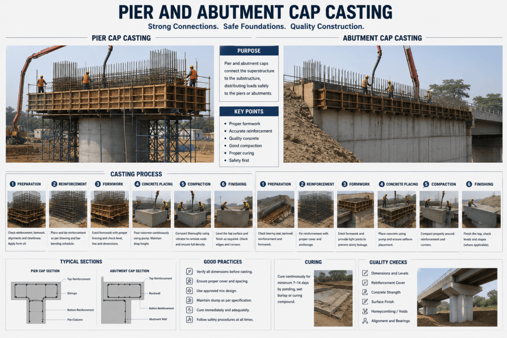
Pier & Abutment Cap Casting Procedure as per Bridge Construction Standards

Methodology for Casting of Pier / Abutment Cap 1. Survey After completion of pier or abutment shaft casting, centerlines in both longitudinal and transverse directions shall be marked on the top surface of the pier shaft for fixing of reinforcement and formwork for pier/abutment cap. Survey coordinates, centerline, and levels shall be checked with reference to approved drawings and control points. Top level and alignment of pier shaft shall be verified before commencement of cap works. Reference markings shall be used for accurate placement of reinforcement and shuttering. 2. Reinforcement Work 2.1 Preparation of BBS Bar Bending Schedule (BBS) shall be prepared as per approved structural drawings. The BBS shall be submitted to the AE for approval before fabrication. 2.2 Cutting & Bending Reinforcement bars shall be cut according to approved BBS using cutting machines or manually. Bars shall be bent as per approved bending details. Cutting and bending may be carried out at rebar yard or site depending upon site conditions. Reinforcement bars shall be cleaned properly before placing. 2.3 Fixing of Reinforcement Reinforcement shall be fixed manually as per approved drawings. Prefabricated reinforcement cages may be transported and erected to reduce cycle time. Cover blocks, spacers, and chairs shall be provided to maintain required cover. Proper anchorage, lap lengths, and spacing shall be ensured before concreting. Reinforcement inspection shall be carried out jointly with the AE before shuttering closure. 3. Formwork Formwork shall be fabricated and erected in accordance with approved drawings and specifications. Standard steel shuttering shall be used wherever possible. Special shuttering shall be fabricated wherever required. All shutter joints shall be connected properly using bolts. Rubber strips or foam strips shall be provided at joints to prevent grout leakage during concreting. Adequate lateral supports, tie rods, and bracings shall be provided to resist pressure of fresh concrete. Gaps and holes in formwork shall be sealed using foam, putty, or suitable materials to make shuttering leak-proof. Formwork surfaces shall be cleaned thoroughly before application of approved shuttering oil. Wire ropes, turn buckles, or chain pulley arrangements shall be used for verticality and alignment adjustment. Formwork shall be checked as per IRC SP:112 checklist before concreting. RFI shall be raised for inspection and approval by the AE. 4. Concreting Concrete of approved grade shall be produced at batching plant using approved mix design. Concrete shall be transported using transit mixers. Slump shall be maintained between 80 mm and 130 mm at pouring location. Regular slump tests shall be conducted during concreting operations. Concrete shall be placed using concrete pump with flexible hose or crane and bucket arrangement. Free fall of concrete shall not exceed 1.5 m. Concrete shall be compacted using 40 mm / 60 mm diameter needle vibrators. Concrete cubes shall be cast and tested for compressive strength as per Clause 1718 of MoRTH Specifications. Suitable shear keys shall be provided at horizontal construction joints. Surface of previous lift shall be roughened and cleaned to remove laitance for proper bonding. Continuous concreting shall be ensured to avoid cold joints. 5. De-shuttering De-shuttering shall be carried out only after the concrete attains required strength. Shuttering removal shall be done carefully using cranes or suitable lifting arrangements. Bolts and supports shall be loosened gradually to prevent damage to concrete surfaces. Edges, corners, and exposed concrete surfaces shall be protected during de-shuttering. Surface defects, if any, shall be repaired immediately after shutter removal. 6. Curing Concrete curing shall commence immediately after de-shuttering. Hessian cloth shall be wrapped around exposed concrete surfaces and kept continuously wet. Top surfaces shall be cured by direct watering or ponding. Curing shall continue for a minimum period of 14 days. Approved curing compounds may also be used where necessary. 7. Deployment of Equipment Batching Plant Transit Mixer Concrete Pump Welding Generator Concrete Vibrator Vibrator Needles Crane Truck / Trailer Bar Bending Machine The quantity and capacity of equipment shall be decided by the site team based on project requirements and construction schedule. 8. Quality Control Survey & Centerline Verification Reinforcement Inspection Cover Block & Spacer Check Formwork Alignment & Verticality Check Concrete Slump Test Concrete Cube Testing Inspection of Construction Joints Surface Finish Inspection Dimensional Tolerance Check 9. Safety All safety precautions shall comply with relevant IRC and MoRTH Specifications. Workers shall wear PPE including helmets, gloves, safety shoes, reflective jackets, and safety belts. Safe working platforms and access arrangements shall be provided. Concrete pumps, cranes, and lifting tools shall be inspected before use. Barricading and caution signage shall be maintained around work areas. Proper illumination shall be provided during night operations. Traffic diversion and safety arrangements shall be implemented where required.

Pier & Abutment Cap Casting Procedure as per Bridge Construction Standards Read More »

Structure
pile foundation

Methodology for Bridge Pile Foundation

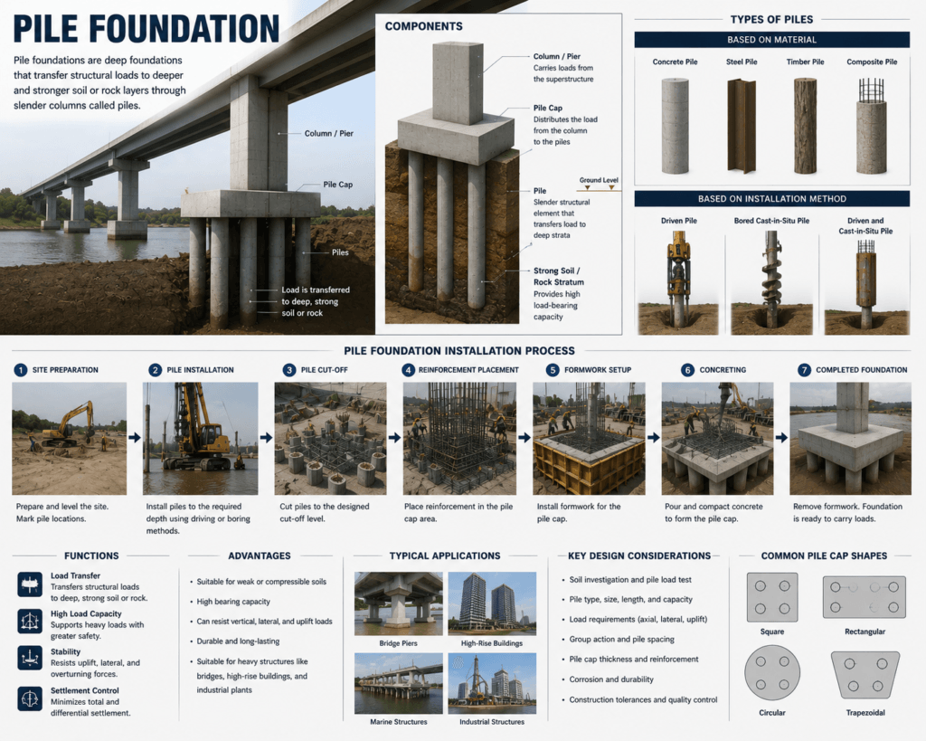
Methodology for Bridge Pile Foundation 1. Scope This method statement covers boring and construction of pile foundations for Minor Bridges and ROBs in accordance with approved drawings, IS:2911 (Part-1), and MoRTH Specifications. The work includes boring, reinforcement fixing, tremie concreting, and quality control of cast-in-situ bored piles. 2. References Contract Agreement IRC: SP: 84-2014 MoRTH Specifications (5th Revision) Relevant Approved Drawings IS:2911 (Part-1) 3. Setting Out The center line and benchmark of each bridge/structure shall be established with reference to project center line and approved by the AE. Reference points for X-X axis and Y-Y axis shall be fixed using Total Station. At least two permanent benchmark/reference points shall be established on either side of the bridge at safe locations away from construction activities. Center line and benchmark points shall be transferred to each pier and abutment location while maintaining safe offset distances. Pile layout shall be established using approved coordinates before commencement of boring operations. All working reference points shall be checked jointly with the AE and recorded in site records. 4. Working Drawings Working drawings, structural drawings, and relevant details shall be submitted to the AE before commencement of work. After review and approval by the AE, setting out and construction activities shall be carried out. Test piles shall be executed as per reviewed drawings and Clause 1105 of MoRTH Specifications. 5. Materials All materials shall conform to Section 1000 of MoRTH Specifications. Structural steel shall conform to Section 1600. Concrete shall conform to Sections 1700, 1800, and 1900. Reinforcement steel shall conform to approved drawings and relevant IS codes. 6. Equipment & Machinery Piling Rig / Percussion Machine Lifting Crane Dumpers Batching & Mixing Plant Transit Mixer Concrete Pump Concrete Vibrators Vibrator Needles Bar Bending Machine 7. Personnel for Execution & Supervision Experienced and trained personnel shall be deployed for pile construction activities. Reinforcement cage inspections shall be carried out by the Sr. Structural Engineer / DPM to ensure compliance with approved drawings and specifications before lowering into boreholes. 8. Construction Operations 8.1 Boring Operations Cast-in-situ bored piles shall be constructed by boring into the ground and removing excavated material. Boring shall be carried out using rotary drilling equipment. Pile diameter shall not be less than specified in approved drawings. Continuous records shall be maintained regarding boring depth and volume of concrete placed. Bentonite slurry or approved drilling mud shall be maintained above groundwater level throughout boring operations to ensure bore stability. Borehole verticality and alignment shall be checked periodically during drilling. 8.2 Reinforcement Cage Lowering Reinforcement cages shall be fabricated as per approved BBS and drawings. Cover blocks and spacers shall be fixed to maintain required cover. The reinforcement cage shall be lowered carefully without disturbing bore stability. Proper lifting arrangements shall be used during cage lowering operations. 8.3 Concreting Operations Wherever practicable, concrete shall be placed in a clean and dry borehole. Before concreting, it shall be ensured that no loose material or debris remains at the bottom of the bore. Concrete shall be placed using tremie pipe continuously from pile toe to pile top. The bottom end of tremie pipe shall always remain embedded in freshly placed concrete. Concrete placement shall be continuous without interruption to avoid cold joints. Concrete shall be properly graded and self-compacting. Care shall be taken to avoid segregation or contamination of concrete. Concrete placing rate shall not be less than 6 m pile length per hour. Temporary casing during concreting shall conform to Clause 1107.3 of MoRTH Specifications. Where concrete is placed in dry boreholes with casing, top 3 m concrete shall be compacted using internal vibrators. 9. Mixing, Transportation, Placing & Compaction of Concrete 9.1 Concrete Mixing Concrete shall be produced in approved batching and mixing plants as per Clause 1708 of MoRTH Specifications. Batching plant calibration shall be approved by the AE. Mixing time shall ensure uniform color and consistency. Mixers not used for more than 30 minutes shall be cleaned before reuse. Water-cement ratio shall be maintained considering aggregate moisture content. Approved superplasticizers conforming to Section 1012 shall be used where required. 9.2 Transportation of Concrete Concrete shall be transported using transit mixers. Concrete pouring shall be avoided during extreme summer and winter temperatures. Concrete temperature during placement shall remain between 5°C and 40°C. Concreting shall not be carried out when ambient temperature exceeds 40°C. 9.3 Placing & Compaction Concrete shall be placed as near as possible to final position. Concrete shall not be dropped freely from height exceeding 1.5 m. Concrete shall be placed in layers of maximum 300 mm compacted thickness. Fresh concrete shall not be placed against concrete older than 30 minutes without proper construction joints. Formwork and reinforcement shall be cleaned before concreting. 10. Quality Control Pile Location & Verticality Check Bore Depth Verification Bentonite Slurry Testing Reinforcement Cage Inspection Concrete Slump Test Concrete Cube Testing Tremie Concreting Monitoring Pile Integrity Test (PIT) / Load Test as Applicable Tolerances shall conform to Clause 1116.1 of MoRTH Specifications 11. Safety Barricading and warning signage shall be provided around piling locations. All lifting equipment and machinery shall be inspected before use. Workers shall use PPE including helmets, safety shoes, reflective jackets, gloves, and safety belts. Proper illumination shall be provided during night operations. Safe lifting procedures shall be followed during cage lowering and casing operations. Emergency rescue arrangements shall be maintained at site during piling operations.

Methodology for Bridge Pile Foundation Read More »

Structure

Methodology for Pile Cap

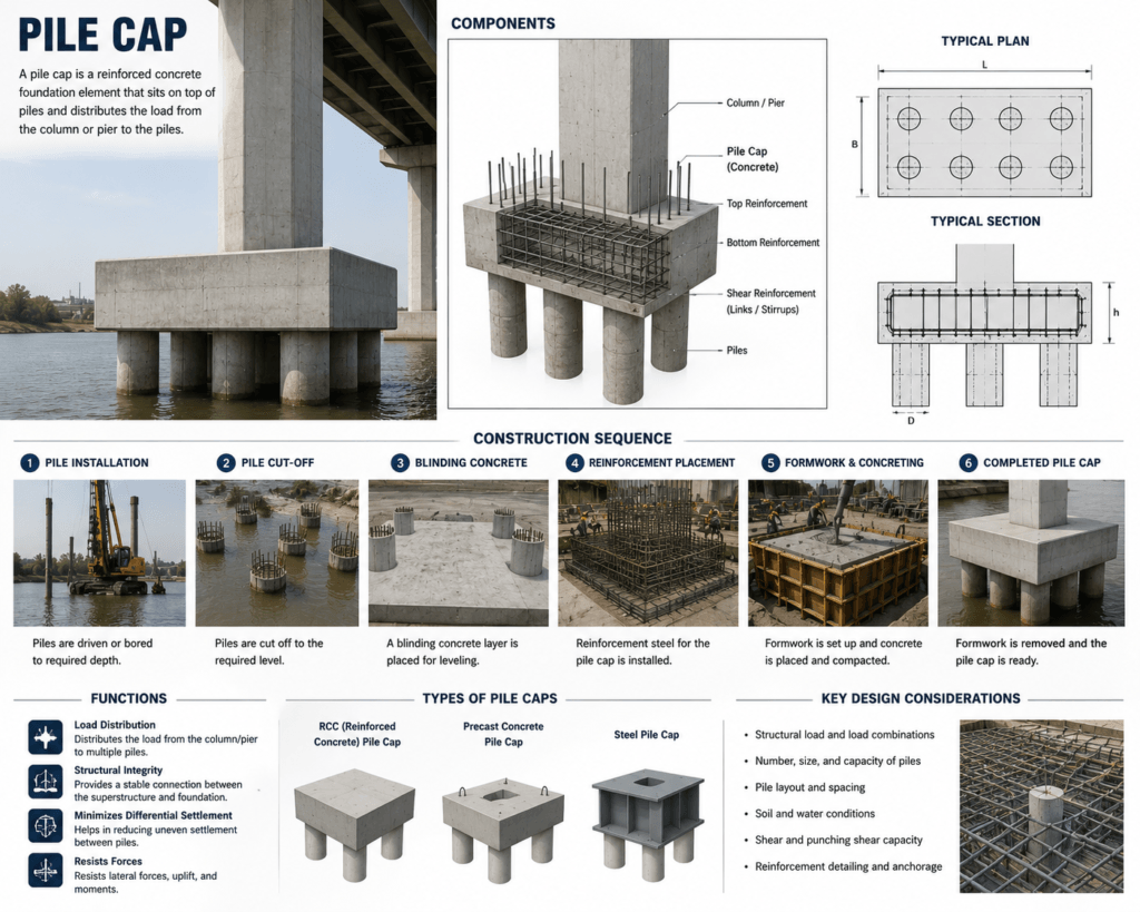
Methodology for Pile Cap 1. Survey Before commencement of excavation, the pile cap area shall be marked on the ground with reference to approved control points and drawings. After excavation, pit levels shall be checked and recorded as per approved drawings. Longitudinal and transverse center lines shall be marked outside the excavation pit for reference and cross-checking of pile positions. Pile shift shall be recorded by marking theoretical pile coordinates and comparing actual pile positions. A circle equivalent to pile diameter shall be drawn to measure pile deviation. As-built details of piles shall be jointly recorded. Based on pile location, PCC and pile cap layout shall be marked ensuring minimum 150 mm offset from pile edge. After laying PCC, pile cap layout shall be transferred on PCC surface to facilitate reinforcement fixing and shuttering erection. 2. Excavation Excavation shall be carried out as per approved drawings and required dimensions. Shoring arrangements shall be provided depending on soil stability conditions. Steel plates and props shall be used for shoring wherever required. Excavation dimensions shall provide sufficient working space around pile cap. Last 300 mm excavation shall be carried out manually. Levelling course shall be laid within 36 hours after completion of final excavation. A sump of approximately 750 mm depth below PCC level shall be provided for dewatering. Earthen drains shall be provided around excavation if required to divert rainwater and seepage water. Water table shall be maintained at least 300 mm below excavation level before PCC laying. Excavated earth shall be disposed using dumpers/loaders at approved dumping locations. 3. Removal of Laitance Pile head laitance shall be removed after pile casting to expose sound concrete. Pneumatic jack hammers may be used after 7 days of pile casting. Manual chipping may be carried out after 3 days of pile casting. Pile top shall project minimum 50 mm into pile cap as per IRC:78 Clause 709.5.2. Pile reinforcement shall be fully anchored into pile cap. Broken concrete debris shall be removed and disposed at approved locations. Exposed reinforcement bars shall be cleaned and straightened using wire brush. 4. PCC (Plain Cement Concrete) After levelling the foundation surface, PCC shall be laid as per approved drawings. Foundation surface shall be watered before PCC placement. PCC of M15 grade or specified grade shall be produced in batching plant and transported using transit mixers. Concrete shall be poured through chutes and levelled manually. PCC shall extend at least 100 mm beyond pile cap edges to facilitate shuttering. PCC levels shall be jointly checked and verified. PCC curing shall be carried out by sprinkling water. 5. Reinforcement 5.1 Fabrication Bar Bending Schedule (BBS) shall be prepared as per approved drawings. Reinforcement shall be cut and bent at rebar yard or site as required. Fabricated reinforcement shall be transported safely to site. 5.2 Fixing of Reinforcement Reinforcement shall be fixed manually as per approved drawings. Pile reinforcement shall be lapped with pile cap reinforcement. Cover blocks of same grade concrete shall be provided at approximately 2 m c/c spacing. Bars shall be tied using GI binding wire. Pier shaft reinforcement shall be erected after fixing pile cap reinforcement. Suitable staging frames shall be used for supporting pier reinforcement cages. Reinforcement cage inspection shall be carried out jointly with AE as per IRC SP:112 checklist. Sufficient chairs and spacers shall be provided to maintain cage position and cover. Pier dowels shall be fixed rigidly to prevent buckling or displacement. 6. Shuttering Shuttering shall be fabricated and erected as per approved drawings. Shuttering locations shall be marked based on pile cap layout over PCC. Shuttering surfaces shall be cleaned with wire brush before erection. Approved shuttering oil shall be applied before fixing. Rubber strips or foam strips shall be provided at joints to prevent slurry leakage. Adequate side supports, bracings, and tie bars shall be provided to resist concrete pressure. Shuttering alignment, dimensions, and supports shall be checked before concreting. 7. Concreting Concrete of approved grade shall be produced at batching plant and transported using transit mixers. Slump shall be checked at pouring location and maintained between 80 mm and 130 mm. Concrete shall be placed using concrete pump, placer boom, or chutes. Concrete placement shall proceed continuously from one end to another. Free fall of concrete shall not exceed 1.5 m. Concrete shall be compacted using 40 mm / 60 mm needle vibrators. Concrete cubes shall be cast for compressive strength testing as per IRC:21. Successive layers shall be placed before initial setting of previous layer to avoid cold joints. Regular tamping and vibration shall be ensured throughout concreting operations. 8. Curing Date of casting shall be marked on concrete surface to monitor curing duration. Concrete curing shall be carried out using ponding method. Bunds shall be prepared using lean cement mortar after initial setting. Bunds shall be filled continuously with water from approved source. Pile cap sides shall be covered with wet hessian cloth until backfilling starts. Backfill soil shall also be kept moist to continue curing effect. 9. Backfilling Backfilling shall commence after de-shuttering and joint inspection approval. Backfilling shall be carried out using approved excavated material or local soil. Soil shall be placed in layers not exceeding 150 mm compacted thickness. Compaction shall be carried out using mechanical tampers, rammers, or plate compactors. Watering shall be done as required to achieve proper compaction. Compacted density shall not be less than pre-excavation field density. 10. Miscellaneous Works Damaged roads and approaches shall be repaired immediately after backfilling. Road restoration shall preferably be completed within 15 days of backfilling. Barricades shall be removed only after completion of restoration work. Entire work area shall be cleaned after completion of activities. 11. Construction Machinery Excavator Dumper Transit Mixer Batching Plant Truck / Trailer Welding Generator Concrete Vibrator Concrete Needles Jack Hammer Compressor Crane / Hydra Dewatering Pump 12. Quality Control Survey & Layout Verification Excavation Level Check Reinforcement Inspection Cover Block & Spacer Check Shuttering Alignment Check Concrete Slump Test Concrete Cube Testing Pile Position & Offset Verification

Methodology for Pile Cap Read More »

Structure
piershaft

Methodology for Casting of Pier / Abutment Shaft Work Procedure

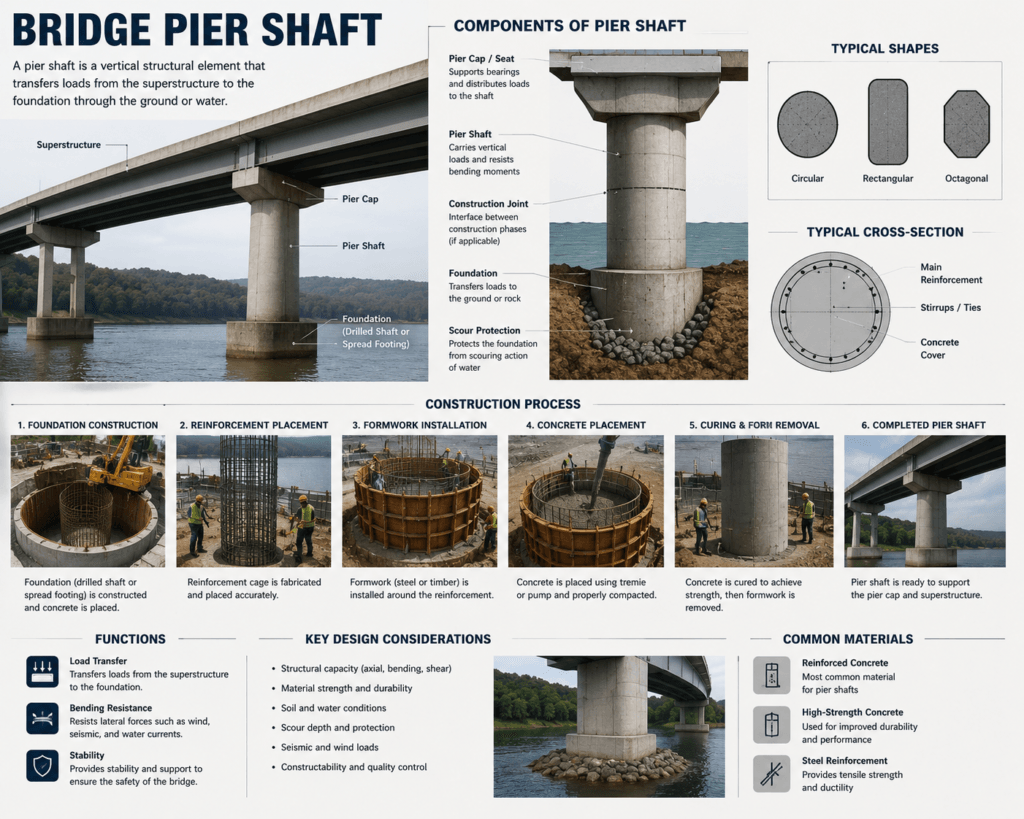
Methodology for Casting of Pier / Abutment Shaft Methodology for Casting of Pier / Abutment Shaft 1. Survey The location and layout of pier and abutment shafts shall be checked with reference to established control points and benchmarks created during pile foundation works. Longitudinal and transverse centerlines shall be verified before commencement of reinforcement and shuttering work. Survey coordinates and offsets shall be cross-checked with approved drawings. Levels and alignment shall be jointly verified with the AE before starting construction. 2. Reinforcement Work 2.1 Preparation of BBS Bar Bending Schedule (BBS) shall be prepared as per approved structural drawings. Submitted to AE for approval before fabrication. 2.2 Cutting & Bending Reinforcement bars shall be cut as per approved BBS using manual or machine cutting. Bars shall be bent as per approved shapes and dimensions. All reinforcement shall be cleaned before use. 2.3 Fixing of Reinforcement Reinforcement shall be placed and tied as per drawings. Prefabricated cages may be used for faster execution. Cover blocks, spacers, and chairs shall be provided for required cover. Check spacing, laps, anchorage, and verticality before concreting. 3. Formwork Formwork shall be fabricated as per approved drawings to maintain shape and alignment. Standard steel shuttering shall be used wherever possible. Joints shall be bolted and sealed using rubber/foam strips to prevent leakage. Adequate bracing and supports shall be provided against concrete pressure. Formwork shall be cleaned and shuttering oil applied before erection. Alignment and verticality shall be checked as per IRC SP:112 checklist. RFI shall be raised before concreting for AE approval. 4. Concreting Concrete shall be produced at batching plant using approved design mix. Transported using transit mixers to site. Slump shall be maintained between 80 mm to 130 mm. Concrete shall be placed using pump or crane bucket. Free fall shall not exceed 1.5 m. Compaction shall be done using 40/60 mm vibrators. Cubes shall be cast as per MoRTH Clause 1718. Construction joints shall be properly roughened and cleaned. Concreting shall be continuous to avoid cold joints. 5. De-shuttering Formwork shall be removed only after achieving required strength. Removal shall be done carefully using crane or manual tools. Edges and corners shall be protected during stripping. Defects shall be repaired immediately after removal. 6. Curing Curing shall start immediately after de-shuttering. Vertical surfaces shall be covered with wet hessian cloth. Continuous water sprinkling shall be ensured. Top surfaces shall be water cured or ponded. Minimum curing period shall be 14 days. Curing compound may be used where required. 7. Deployment of Equipment Batching Plant Transit Mixer Concrete Pump Welding Generator Concrete Vibrator & Needles Crane Truck / Trailer Bar Bending Machine Equipment deployment shall depend upon site requirement and construction schedule. 8. Quality Control Survey & alignment verification Reinforcement inspection Cover block & spacer check Formwork alignment & verticality check Concrete slump test Cube strength testing Construction joint inspection Surface finish inspection Dimensional tolerance check 9. Safety Compliance with IRC and MoRTH safety standards PPE: helmet, shoes, gloves, jacket, safety belt Secure working platforms and ladders Inspection of pumps and lifting equipment Barricading and signage at work zones Adequate lighting for night work Traffic diversion where required ITP for Pier / Abutment Shaft Construction Inspection & Test Plan (ITP) Pier / Abutment Shaft Construction Works (RCC Bridge Works) Legend: H = Hold Point (Work cannot proceed without approval) W = Witness Point (Engineer may witness) R = Review/Record verification 1. Setting Out & Survey Works Activity Inspection Requirement Reference Responsibility Type Verification of centerline & coordinates Check against approved drawings GFC Drawings Contractor / Engineer H Level & TBM confirmation Benchmark validation Survey SOP Surveyor / Engineer W Staking of pier/abutment location Accuracy of layout (tolerance check) IRC SP-13 Engineer H 2. Excavation / Foundation Works Activity Inspection Requirement Reference Responsibility Type Excavation level & dimensions As per drawing limits GFC Drawings Engineer H Soil bearing strata verification Geotechnical confirmation Geotech Report Engineer / Geotech H Blinding concrete Thickness & level check Specs Engineer W 3. Reinforcement Work Activity Inspection Requirement Reference Responsibility Type BBS approval Bar cutting & bending verification Approved Drawings Engineer H Reinforcement placement Spacing, cover, lap length IRC:112 Engineer W Final cage inspection Before shuttering closure GFC Drawings Engineer H 4. Formwork / Shuttering Activity Inspection Requirement Reference Responsibility Type Formwork design approval Structural stability check IS 14687 Engineer H Erection & alignment Verticality & leakage control Method Statement Engineer W Final shuttering approval Pre-pour inspection QA/QC Engineer H 5. Concreting Works Activity Inspection Requirement Reference Responsibility Type Concrete mix design Approval of design mix IRC / MORTH Engineer H Slump test Workability check IS 1199 QA/QC W Cube casting 7 & 28 day strength test IS 516 QA/QC W Concrete pouring approval Pre-pour clearance Method Statement Engineer H 6. Curing & Finishing Activity Inspection Requirement Reference Responsibility Type Curing method Water/compound curing Specs Engineer W Minimum curing period 7–14 days compliance IRC Engineer R Surface finishing Honeycomb inspection QA/QC Engineer W 7. Final Inspection Activity Inspection Requirement Reference Responsibility Type Dimensional check Verticality & alignment GFC Drawings Engineer H Surface inspection No cracks/honeycombing QA/QC Engineer W As-built documentation Final record submission QA System Contractor H Summary: Hold Points: Layout approval, foundation approval, reinforcement inspection, shuttering approval, pre-pour clearance, final inspection Witness Points: Survey checks, reinforcement placement, testing, concreting, curing

Methodology for Casting of Pier / Abutment Shaft Work Procedure Read More »

Structure

© 2026 HIGHWAY QUALITY TEST. All rights reserved.

WhatsAppNeed Help?
Scroll to Top