
HIGHWAY QUALITY TEST

Precision Testing. Proven Quality. Safer Infrastructure.

fineness of cement

Fineness of Cement Test as per IS 4031 – Procedure, Formula & Importance

🧪 Determination of Fineness of Cement IS 4031 (Part 3) 🎯 Objective To determine the fineness of cement by dry sieving method using 90 micron IS sieve as per IS 4031 (Part 3). 🛠 Apparatus Required Standard balance with 100 g weighing capacity IS 90 micron sieve Soft sieve brush Cement sample ⚙ Test Procedure Break down any air-set lumps in the cement sample gently with fingers. Accurately weigh 100 g of cement sample. Place the sample on a standard 90 micron IS sieve. 📷 Laboratory Fineness Test of Cement using 90 Micron IS Sieve Continuously sieve the sample for 15 minutes. Collect and weigh the residue retained on the sieve after sieving. 📐 Calculation The percentage residue by weight over the total cement sample is reported as the fineness of cement. % Weight of Residue = (Weight of Sample Retained on Sieve × 100) ———————————————- Total Weight of Cement Sample 📊 Permissible Limits The percentage residue retained on 90 micron sieve should NOT exceed 10%. 💡 Importance of Test Fineness of cement directly affects the rate of hydration, heat generation, setting time, and strength development of concrete. Finer cement provides higher early strength but may increase shrinkage and heat of hydration. This test is essential for NHAI, MoRTH, bridge, highway, and structural QA/QC works. 🧪 IS 4031 • IS 516 • MoRTH • NHAI QA/QC Complete Cement Laboratory Test Series Sequential cement testing procedures performed as per Indian Standard Codes for concrete quality assurance in highway, bridge, rigid pavement, structural, and infrastructure projects. 🔬 IS 4031 (Part 1) STEP 1 Fineness of Cement Determination of cement particle fineness using 90 micron IS sieve and Blaine air permeability method. ⚙️ IS 4031 (Part 4) STEP 2 Standard Consistency Determination of optimum water percentage using Vicat apparatus. ⏱️ IS 4031 (Part 5) STEP 3 Initial Setting Time Measurement of initial hardening stage using Vicat needle penetration. 🧱 IS 4031 (Part 5) STEP 4 Final Setting Time Determines complete hardening stage of cement paste. 📏 IS 4031 (Part 3) STEP 5 Soundness Test Le Chatelier method for determining expansion characteristics of cement. 💪 IS 4031 (Part 6) STEP 6 Compressive Strength Mortar cube compressive strength evaluation at different curing ages. 📌 Quality Control Insight Cement testing must be performed in proper IS code sequence to establish accurate correlation between fineness, consistency, setting characteristics, soundness, and strength development. Sequential testing is mandatory during NHAI, MoRTH, bridge, highway, rigid pavement, and third-party QA/QC inspections.

Fineness of Cement Test as per IS 4031 – Procedure, Formula & Importance Read More »

Cement
bridge repair

Bridge Repair & Rehabilitation Methodology

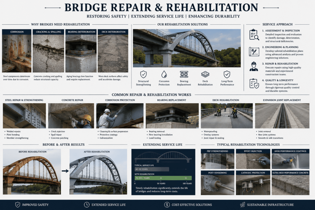
Methodology on Repair / Rehabilitation of Existing Bridge Structures The current methodology may be referred for the repair, rehabilitation and strengthening of the existing bridge structures. It shall be read in conjunction with the provisions specified in IRC SP: 40-1993 (Guidelines for Techniques for Strengthening and Rehabilitation of Bridges) for detailed understanding and implementation. The broad methodology for repair and rehabilitation of existing structures along the project highway is described below: 1. Repair / Remedial Measures for Concrete Crash Barriers & Parapets Observation The crash barriers / parapets are generally well constructed and erected at site. However, at some locations improper finishing and partial damages have been observed. Remedial Measures Surface Preparation: The damaged surface shall be prepared by mechanical methods such as chipping, sand blasting and compressed air cleaning. Minor Surface Repair: Edges and minor damaged portions of crash barriers / parapets shall be repaired using 1:4 cement mortar. Major Surface Repair: For severely damaged portions, repairs shall be carried out using concrete of same or higher grade matching the existing material. If the damage is extensive, the affected portion shall be demolished and reconstructed. 2. Restoration of Rusted / Exposed Reinforcement of Slab Observation Overall condition of slab is satisfactory; however, at some locations the concrete cover has spalled off exposing reinforcement bars to atmosphere. Remedial Measures Surface Preparation: Concrete cover shall be removed by chipping, sand blasting and compressed air cleaning until reinforcement is fully exposed. Repair Procedure: Rust from reinforcement shall be removed using sand blasting, wire brushing or needle hammer. Reinforcement shall be protected against corrosion by epoxy coating or alkaline cementitious bond coat. Where sufficient thickness is available, damaged portions shall be repaired using concrete one grade higher than the existing concrete. If sufficient thickness is not available, polymer cement mortar shall be used. 3. Repair of Foundation General methodology for repair and strengthening of foundations depends upon the site conditions and nature of distress. Typical Repairs Scour and erosion protection. Repair of washed away or damaged protection works. Repair of foundations on soft ground subjected to erosion. Repair of serrated surfaces caused by high velocity flow carrying abrasive particles. Observation Excessive scour is one of the major causes of structural distress or failure in bridge foundations. The extent of damage depends upon stream bed material, discharge intensity, silt content, flow obliquity and shape of structure. Remedial Measures Scour around pier foundations shall be controlled using garlanding techniques by placing heavy concrete blocks, stone boulders, sheet piling or stone pitching around the foundation. 4. Repair of Substructure of Minor Bridges Observation Deterioration of joints, spalling and disintegration of abutment wall surfaces have been observed. Remedial Measures Damaged joints shall be repaired by epoxy mortar injection, surface protection treatment and plastering with 1:4 cement mortar on the affected surfaces. 5. Repair of Concrete For partial depth repairs, deteriorated concrete shall be removed up to 75 mm to 100 mm depth and approximately 1 m × 1 m area depending upon extent of damage. The repaired area shall be filled with elastomeric concrete or polymer concrete of one grade higher than existing concrete. Chicken mesh reinforcement fixed using U-clips shall be provided to improve bonding and durability. 6. Repair of Cracks Observation Cracks shall be examined to determine whether they are active or dormant. Remedial Measures Active Cracks: Repair by stitching, jacketing, epoxy injection and epoxy mortar treatment. Dormant Cracks: Repair by grouting, jacketing and thin resurfacing treatment. 7. Repair of Drainage Spouts Repair or replacement of drainage spouts shall be carried out based on actual site condition and approved drawings. 8. Replacement of Approach Slab Replacement of approach slab shall be decided based on site condition, structural distress and recommendations of the Engineer. 9. Repair / Replacement of Bearings & Expansion Joints Repair or replacement of bearings and expansion joints shall be carried out strictly in accordance with manufacturer’s specifications, approved drawings and vendor recommendations.

Bridge Repair & Rehabilitation Methodology Read More »

Structure

Top QA/QC Site Mistakes Engineers Must Avoid

Top QA/QC Site Mistakes Engineers Must Avoid ⚡ Quick Summary ✔ Identify common QA/QC mistakes ✔ Understand their impact on projects ✔ Learn how to avoid costly errors ✔ Improve overall site quality Mistakes in QA/QC can lead to serious consequences such as project delays, rework, financial loss, and even structural failure. Understanding these common errors will help you become a more efficient and reliable site engineer. ❌ Skipping Material Testing Ignoring required tests can result in using poor quality materials on site. Impact: Weak structure, early failure Solution: Always follow testing frequency as per specifications ❌ Improper Compaction Inadequate compaction reduces strength of soil and pavement layers. Impact: Settlement, cracks, pavement failure Solution: Ensure proper rolling and density checks (FDT) ❌ Using Unapproved Materials Using materials without approval or testing can compromise quality. Impact: Rejection of work, penalties Solution: Use only approved and tested materials ❌ Poor Documentation Missing or incorrect records can lead to rejection even if work is good. Impact: Audit issues, claim rejection Solution: Maintain proper and updated records ❌ Ignoring Specifications Not following MoRTH/IS codes leads to non-compliance. Impact: Work failure and re-execution Solution: Always follow approved drawings and specifications ⚠️ Key Takeaway Most site failures happen due to small mistakes repeated daily. A disciplined QA/QC system can prevent major losses. 💡 Pro Tip: Test → Record → Approve → Then Execute ⚠️ Free Download Get QA/QC Checklist to avoid common site mistakes Download Checklist 🔒 Want Complete QA/QC System? Unlock SOPs, checklists, formats & advanced tools used by professionals Upgrade to Starter Bundle @299

Top QA/QC Site Mistakes Engineers Must Avoid Read More »

FAQ/Interview

Method Statement for Dismantling Culverts, Bridges, Pavements and Other Structures

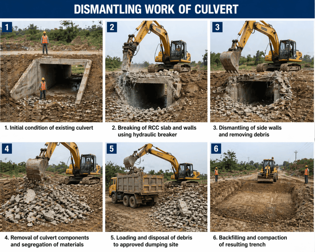
Method Statement for Dismantling Culverts, Bridges, Pavements and Other Structures [last_updated] 1. Purpose The purpose of this Method Statement is to define the detailed construction methodology for dismantling culverts, bridges, pavements, kerbs, and other structures in accordance with the provisions of MoRTH Clause 202 and relevant amendments in the Technical Specifications. 2. Scope of Work The work shall consist of removing existing culverts, bridges, pavements, kerbs, and other structures that interfere with new construction activities or are unsuitable to remain in place. The work shall also include salvaging, disposal of dismantled materials, and backfilling of resulting trenches and pits. Existing structures located within the highway limits and designated for removal shall be dismantled up to the extent shown in the Good for Construction (GFC) drawings or as directed by the Authority Engineer. Dismantling operations shall be carried out using suitable equipment such as backhoe loaders, excavators, dozers, graders, tractor dozers, jackhammers, or excavators fitted with rock breakers, depending upon the type of structure. Care shall be taken to avoid disturbance or damage to adjacent pavements, structures, underground utilities, and any work intended to remain in place. All dismantling operations that may affect new construction shall be completed before commencement of new works. Traffic diversion, safety arrangements, and traffic management measures shall be implemented as per approved methodology prior to dismantling activities. Dismantling work shall commence only after obtaining approval from the Authority Engineer. 3. Sequence of Operations 3.1 Dismantling of Culverts and Bridges Existing culverts and bridges shall be dismantled carefully to prevent damage to reusable materials, portions of structures to be retained, nearby properties, and adjacent structures. Where existing culverts or bridges are to be extended or incorporated into the new work, only the required portion shall be removed as directed by the Authority Engineer. Connecting edges shall be cut, chipped, and trimmed to the required alignment and levels without weakening the remaining structure. Reinforcement bars intended for future connection as dowels or ties shall be protected from damage during dismantling operations. Pipe culverts shall be dismantled carefully to avoid breakage or damage to the pipes. 3.2 Dismantling of Pavements and Other Structures Existing pavements, kerbs, gutters, and other structures shall be dismantled as specified in the drawings and Technical Specifications. Portions intended to remain in service shall be cut neatly along straight lines or existing joints with faces perpendicular to the pavement surface. Sufficient dismantling shall be carried out to achieve proper grades, alignment, and connection with the proposed works. Concrete pavements, bituminous pavements, shoulders, and base courses designated for dismantling shall be broken into pieces not exceeding 0.02 cubic metres. Dismantled materials shall either be stockpiled at approved locations for reuse or disposed of as directed by the Authority Engineer. Holes, depressions, and excavated areas resulting from dismantling operations shall be backfilled using approved material and compacted to the specified density. Disposal of dismantled materials shall be carried out in accordance with the relevant Technical Specifications and environmental requirements. 4. Equipment Used Backhoe Loader Excavator Bull Dozer Tractor Dozer Motor Grader Jack Hammer Excavator with Rock Breaker

Method Statement for Dismantling Culverts, Bridges, Pavements and Other Structures Read More »

Concrete Work

METHOD STATEMENT FOR SURVEY WORK

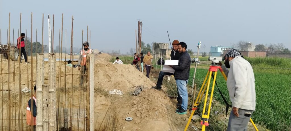
SCOPE: Survey Procedure Survey Sequence The survey is carried out from the starting point to the end point by following the sequence given below: Deriving of coordinates through DGPS. Running of traverse line between two known DGPS points. Reducing the relative levels between two known DGPS points. Staking in of topographical details in three-dimensional coordinates. Depicting of structural cross road details. Layout of reference line for roads and structures. Netting of original ground levels. Reference MoRTH Clause No: 109 and technical specifications of the project shall be followed. Equipments For the above task, the following precision survey instruments are used to maintain the required accuracy: DGPS (Dual Global Positioning System). Electronic Total Station with inbuilt programs (1″ least count accuracy). Auto Level with graduated vertical scale of 5 mm interpolation accuracy. Compass (to indicate North direction or true meridian) with 1 mm precision as directed by the Engineer. Tools Measuring Tape Pegs Nails Hammer Paint Tins Safety Cones Safety Boards Procedure Project reference center line of the proposed cross-section shall be fixed by the surveyor and marked on the ground using nails. Chainage shall be clearly marked on the existing road using paint. This marking shall be carried out at an interval of 20 m on straight portions and 10 m on curved portions. Offsets shall also be marked on the existing road wherever applicable. Further, prior to the commencement of earthwork or structural work, as per MoRTH specification Clause 109.3 and 109.5, the centerline shall be referenced by providing chainage pillars at the Right of Way (ROW) edge. Initial Survey Methodology Initial Survey (Satellite and Topographical) The survey is carried out for fixing of the control network. The following methodology is based on the measurement of angles and distances on a horizontal plane along with satellite geometry. GTS (Great Trigonometrical Survey) Great Trigonometrical Survey (GTS) points are already established by the Survey of India with reference to Mean Sea Level (MSL). DGPS Data (Dual Frequency Global Positioning System) Initially, pairs of ground control points are established at every 5 km interval. These points are connected to the DGPS network to obtain accurate X, Y, Z coordinates for the entire project. Traverse Traversing is carried out by measuring a set of horizontal angles in different quadrants between two straight points. Reciprocal horizontal distances between two points are measured by establishing traverse stations at every 200 m interval. An open traverse is carried out from a fixed DGPS station and closed at another fixed DGPS station. The coordinates (X, Y) are calculated and any misclosure in Easting and Northing is adjusted to maintain the required accuracy. Formula Δ Easting = Sin (North Bearing) × Horizontal Distance Δ Northing = Cos (North Bearing) × Horizontal Distance Double Territory Level Line Auto level instruments are used to determine the relative difference in elevation between two points. The survey is carried out between fixed DGPS datum points to identify misclosure in height. Precision automatic levels, conforming to MoRTH Clause 900 and fitted with micrometer attachments, shall be used for all double run and TBM transfer works to ensure accuracy. Temporary Bench Marks (TBM) Precast pillars of size 150 mm × 150 mm × 750 mm, reinforced with 6 mm bars and provided with a central 8 mm rod (marked with a dot on the top surface), are used as TBM pillars. These pillars are embedded such that 300 mm remains above ground level. Yellow, black, and red paints are used for marking their identification name and number. Traverse Station Traverse stations are marked by fixing a nail at the center and highlighting it with a yellow paint mark on one edge of the existing carriageway surface at every 250 m interval. Each station is assigned a unique identification number. Survey Details – OGL, Calibration & Safety Original Ground Level (OGL) The laid out reference line is taken as “0”. On the longitudinal section (L-section), cross-sections are taken at specified and prescribed offset distances on the original ground. Levels are observed at every 10 m interval in the longitudinal direction and up to PROW in the cross-sectional direction. The RLs (Reduced Levels) of OGL are observed and calculated from a known station and closed on another known station to ensure accuracy. Calibration Internal calibration shall be carried out once every month for leveling instruments and total stations in specified formats. Calibration certificates for level instruments and total stations must be submitted with valid certification from the manufacturer. A “Survey File” containing necessary data such as DGPS details, traversing details, horizontal and vertical control points, reference pillars, survey monuments, and horizontal alignment setting-out details shall be submitted to the Client/Engineer. Responsibility The responsibility for implementation of this procedure lies with the surveyors deployed at various sections for different activities, along with the Survey Engineer and Section In-Charge. Safety Precautions Do not aim the telescope at the sun, as it may damage the EDM of the instrument. Never place the instrument directly on the ground, as it may damage the base. Do not carry instruments along with the stand from one station to another. All safety measures shall be followed as per HIRA (Hazard Identification and Risk Assessment). Avoid heavy shocks and vibrations to the instruments. Remove the battery before storing the instrument in its case. Do not store wet instruments inside the case; allow them to dry before storage. Before removing the instrument from the case, note the layout position to place it back correctly. All staff and workmen shall wear reflective jackets and PPE at the work area. A minimum of 6 cones and a “Men at Work” signboard shall be used during survey work on roads. Staff and workmen shall not use mobile phones while moving on the road. Required safety equipment shall be provided at site to ensure safe working conditions.

METHOD STATEMENT FOR SURVEY WORK Read More »

Survey

Bridge Concrete Superstructure Construction Methodology & QA/QC

Bridge Concrete Superstructure 1. Scope This section covers furnishing and providing concrete superstructure works for bridges including casting, handling, launching of RCC T-Girders, deck slab casting, bearing fixing, expansion joints, and drainage spouts in accordance with approved drawings and MoRTH Specifications. 2. Material All materials used in bridge superstructure works shall conform to Section 1000 of MoRTH Specifications. 3. Casting & Handling of Precast RCC T-Girders 3.1 Fixation of Formwork Firm and level casting beds shall be prepared at site for girder casting. Side shutters shall be erected as per approved girder dimensions. Adequate spacing shall be maintained around girders for de-shuttering and handling. Shuttering shall be cleaned and coated with approved shuttering oil before concreting. 3.2 Preparation & Placing of Reinforcement Cage Bar Bending Schedule (BBS) shall be prepared as per approved drawings. Cutting, bending, and tying of reinforcement shall be carried out as per approved BBS. Reinforcement details shall be checked and recorded before concreting. Approved cover blocks of same grade concrete shall be used. Prestressing ducts, inserts, and embedded items shall be fixed as per drawings wherever applicable. 3.3 Pouring of Concrete Concrete of approved grade shall be produced at batching plant using approved mix design. Concrete shall be transported using transit mixers and poured through chute arrangements. Concrete placement shall proceed continuously from one end to another. Cold joints shall be avoided during concreting. Compaction shall be carried out using 40 mm and 60 mm needle vibrators. Wooden mallets shall be used externally on shutters to remove air voids and honeycombing. 4. Identification of Precast RCC T-Girders Each girder shall be properly marked for identification purposes on both sides. Date of Casting Length of Girder Girder Number 5. Curing & De-positioning of RCC T-Girders Girder curing shall be carried out as per MoRTH Specifications. Continuous curing shall be maintained for specified duration. RCC T-Girders shall be shifted from casting bed after achieving minimum required strength or after 14 days, whichever is applicable. Suitable lifting arrangements shall be used during handling and shifting. 6. Tolerances Item Tolerance Variation in flange thickness ±5 mm Variation in web thickness -5 mm to +10 mm Variation in overall depth or width ±5 mm Variation in girder length ±10 mm or ±0.1% of span length Permissible surface unevenness 5 mm 7. Pedestal Casting & Bearing Fixing Bearing centerlines shall be marked accurately over pier/abutment caps. Pedestal dimensions shall conform to approved drawings. Minimum 150 mm clear offset shall be maintained beyond bearing edges. Shuttering shall be erected to required pedestal dimensions. Anchor pockets shall be provided during pedestal concreting. Pedestals shall be cast approximately 20 mm below finished bearing level. Final leveling shall be done using cement epoxy mortar during bearing installation. 8. Launching of Girders RCC T-Girders shall be lifted using lifting hooks provided at both ends. Two cranes shall operate simultaneously during launching. Girders shall be placed directly over bearings in true alignment. Level, line, and plumb shall be checked after placement. Suitable packing or crib arrangements shall be provided where required. Placed girders shall be adequately braced to prevent movement during deck slab construction. 9. Staging for Casting of Deck Slab 9.1 General Arrangement End diaphragm reinforcement and shuttering shall be completed before deck slab staging. Temporary working platforms shall be erected between girders. Staging shall be fabricated using scaffolding pipes and channels. Needle vibrators shall be used for compaction of diaphragm concrete. 9.2 Cantilever Portion Outer girders shall be provided with holes for insertion of tie rods. Cantilever support frames shall be fixed using threaded tie rods and bolts. Required formwork shall be erected over support frames. 9.3 Inner Portion Deck slab staging shall be supported from girder flanges and not from ground. Wooden blocks shall be fixed on girder bottom flange. H-frames and ISMC channels shall be installed using screw jacks. Proper bracing shall be provided to prevent sliding or instability. Shuttering for diaphragm and slab shall be erected as per approved drawings. Foam strips shall be provided between shutter joints to prevent leakage. Levels shall be checked and adjusted using screw jacks. Approved shuttering oil shall be applied before concreting. Entire staging and shuttering shall be inspected and approved by AE. 10. Reinforcement BBS shall be prepared and approved before commencement of reinforcement work. Cutting and bending shall be checked for correct shape and dimensions. Reinforcement shall be placed as per approved drawings. Drainage spouts and rainwater pipe inserts shall be fixed before concreting. Cover blocks and chairs shall be provided to maintain required cover. Wooden blocks shall be fixed for expansion joint recesses as per approved details. 11. Concreting Concrete shall conform to approved mix design and specified grade. Required slump shall be maintained to achieve proper compaction. Concrete shall be transported using transit mixers and placed using concrete pump or placer boom. Concrete in diaphragm shall be laid in layers not exceeding 500 mm. Concreting shall proceed continuously from one expansion joint towards another. Concrete pump pipeline arrangement shall minimize dismantling and re-fixing during concreting. Proper vibration and compaction shall be ensured throughout concreting operations. 12. De-shuttering of Deck Slab Deck slab shuttering shall be removed after achieving specified strength or after 14 days as per MoRTH Specifications. Shuttering plates and scaffolding pipes shall be removed carefully using chain pulleys and ropes. Temporary working platforms shall be utilized during de-shuttering operations. All removed materials shall be safely lowered and stacked. 13. Deployment of Machinery Concrete Pump Batching Plant Transit Mixers Concrete Vibrators Needle Vibrators Cube Moulds Bar Bending Machine Generator / Electrical Arrangement 14. Installation of Strip Seal Expansion Joint with Sinus Plate Expansion joints shall be installed under supervision of manufacturer/supplier engineer. Installation manuals shall be followed strictly. Joint gap dimensions shall be preset based on installation temperature. Recess dimensions, skew, and levels shall conform to approved drawings. Recess surfaces shall be cleaned thoroughly before installation. Joint assemblies shall be aligned and welded with reinforcement as specified. Concrete around joints shall be compacted and cured properly. Installation brackets shall be removed

Bridge Concrete Superstructure Construction Methodology & QA/QC Read More »

Structure

Wearing Coat Construction Methodology for Bridges as per MoRTH

Methodology of Wearing Coat, Approach Slab & Floor Protection Methodology of Wearing Coat, Approach Slab & Floor Protection Introduction This methodology describes the procedure for execution of wearing coat, approach slab, floor protection works, curtain walls, and backfilling behind structures in accordance with MoRTH Specifications and IRC guidelines. Applicable Standards: MoRTH Specifications Clause 2702.1 (Type-1) IRC: 78 IRC: 89 MoRTH Sections 1600 & 1700 What is Wearing Coat? A wearing coat is the top protective layer provided over the bridge deck or concrete surface to provide smooth riding quality, waterproofing, and protection against traffic wear and weather effects. In bridge construction, the wearing coat is generally made of Bituminous Concrete (BC) laid to a specified thickness as per MoRTH Specifications. The main purpose of the wearing coat is to: Provide smooth and comfortable riding surface Protect bridge deck from water penetration Improve skid resistance and traffic safety Increase durability of bridge deck surface Provide proper drainage through cross slope or camber 1. Methodology of Wearing Coat A layer of Bituminous Concrete (BC) 50 mm thick shall be laid in a single layer as per Clause 2702.1 (Type-1) of MoRTH Specifications. The cross slope in the deck shall be maintained as per approved drawings. For flat deck surfaces, camber/super-elevation shall be achieved by providing a profile making course. The profile making course shall be of the same material as that of the wearing coat. The thickness of the wearing coat at any point shall not be less than that specified in Clause 2702.1 (Type-1) of MoRTH Specifications. Surface preparation and cleaning shall be completed before laying BC. Temperature of bituminous mix and rolling pattern shall conform to approved methodology. Compaction shall be achieved using suitable rollers to obtain specified density and surface finish. What is Approach Slab? An approach slab is a reinforced cement concrete slab constructed between the roadway embankment and bridge structure to provide smooth transition for moving vehicles. It helps in reducing settlement differences between the bridge and the approach road. The approach slab improves riding comfort and prevents sudden bumps at bridge entry and exit locations. Provides smooth transition between road and bridge Reduces impact load on bridge structure Minimizes settlement problems near abutments Improves safety and riding quality 2. Methodology for Approach Slab A reinforced cement concrete slab covering the entire width of roadway shall be provided as an approach slab. Minimum length of approach slab shall be 3.50 m or as per approved drawings. Minimum thickness of slab shall be as per approved drawings. The details of slab shall conform to approved drawings. Cement concrete and reinforcement shall conform to Sections 1600 & 1700 of MoRTH Specifications. The base of approach slab shall be prepared as shown in approved drawings. Proper alignment, level, and compaction of foundation layer shall be ensured before concreting. Concrete shall be properly compacted and cured as per specifications. What is Floor Protection? Floor protection is provided around bridge foundations, culverts, and hydraulic structures to protect the bed surface from erosion, scouring, and water damage caused by flowing water. It generally consists of apron, pitching, and curtain walls. The purpose of floor protection is to: Prevent scouring near foundations Protect river bed and slopes from erosion Improve stability of bridge foundation Increase durability of hydraulic structures 3. Methodology for Floor Protection What is Apron Protection? Apron protection is a layer of heavy stones or concrete blocks laid on the river bed near bridge foundations and retaining structures to prevent scouring caused by flowing water. The apron acts as a protective blanket and helps in maintaining stability of the structure foundation. Prevents erosion of river bed Protects foundation against scouring action Improves structural stability during floods Provides additional protection to floor system 3.1 Apron The surface for apron laying shall be levelled and prepared for the required length and width as shown in drawings. The size of stones shall conform to Clause 5.3.7.2 of IRC: 89. The specific gravity of stones shall not be less than 2.65. The size of stone shall be such that the weight of any fragment shall not be less than 40 kg. The stones shall be hand packed within the specified limits. Voids between stones shall be minimized to ensure stability of apron protection. What is Curtain Wall? A curtain wall is a vertical wall constructed below the floor protection or apron to prevent undermining and seepage below the structure. It is generally constructed using PCC or RCC below upstream and downstream floor levels. The curtain wall helps in: Preventing seepage below floor protection Reducing chances of undermining Improving safety of foundation system Providing additional scour protection 3.2 Curtain Wall Foundation trenches shall be excavated providing adequate working space as per approved drawings. The minimum depth of curtain wall below floor level on upstream side shall be 2.0 m. The minimum depth of curtain wall below floor level on downstream side shall be 2.5 m. The curtain wall shall be constructed in PCC of M15 grade. Concrete shall be placed in properly prepared trench and compacted adequately. Curing shall be carried out as per specifications. 4. Methodology for Backfilling Behind Structures Backfilling shall commence in conformity with Appendix VI of IRC: 78. Backfilling shall be carried out with approved material only after concrete has fully set. Backfilling shall be done carefully to avoid undue thrust on any part of the structure. All spaces between foundation masonry/concrete and excavation sides shall be refilled in layers up to original ground level. The thickness of each compacted layer shall not exceed 150 mm. Compaction shall be carried out using suitable equipment such as mechanical tampers, rammers, or plate vibrators after proper watering. Filter material shall be well packed to a thickness of 300 mm to 600 mm with smaller size towards soil and bigger size towards the structure. Specified density and moisture content shall be maintained during compaction. 5. Quality Control Checks Activity Inspection Requirement Wearing Coat Thickness, temperature, density, cross slope Approach Slab Reinforcement, concrete grade, alignment, curing

Wearing Coat Construction Methodology for Bridges as per MoRTH Read More »

Structure

METHOD STATEMENT FOR ROADWAY EXCAVATION

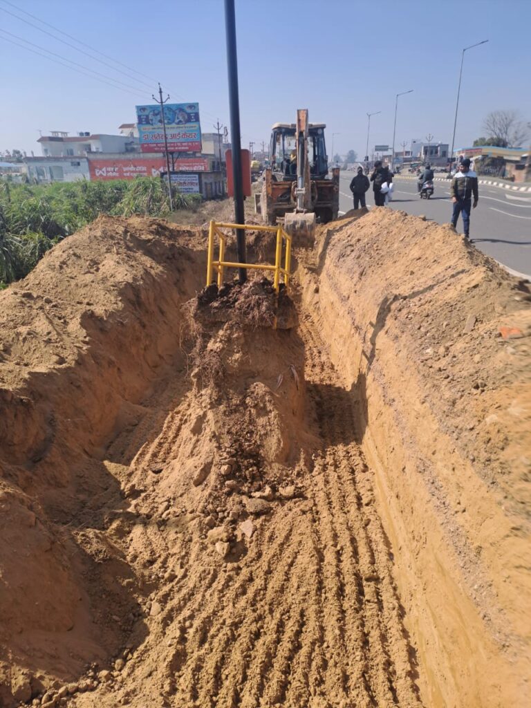
Scope of Work – Excavation Scope  This work shall consist of excavation by mechanical means in all types of soil in final line, level, grades, cross section as shown in drawings for roadways drains, shoulders, median and foundation for structures, including hauling suitable excavation materials to site for embankment and sub grade construction also disposal of unsuitable cut materials specified manner. Reference  MoRT&H Specification clause No 301 to 303 and technical specification of contract Equipment  Excavators, Dumpers, dewatering arrangements Tools  Line rope, lime powder, pegs etc. Manpower & Responsibilities  Construction manager, Earth work engineer/supervisor, land surveyor, material engineer, safety supervisor, helpers Construction Manager He shall be overall responsible for the activity including planning, organising the resources required to carry out the work in consultation with the project manager, implement and ensure safety requirements during the work including that of utility services. Ensures relevant test conducted and records are maintained as per the contract requirements. Coordinate with the consultant engineer in obtaining necessary approvals for the completed activity. Earthwork Engineer / Supervisor Deploying necessary resources at site as planned. Execute the work as per drawing and maintain quality requirements as per specification. Implement and maintain safety regulations and good housekeeping. Coordinate with the consultant staff in obtaining necessary approvals for the completed activity. Land Surveyor Establishing necessary reference points to carry out the work as per the level and alignment. Checking and recording the levels as completed. Coordinate with the consultant staff in obtaining approvals for the finished work. Material Engineer Implement quality procedures as per plan. Ensure the materials used are meeting the specification requirement conduct the required tests as per the relevant specification and maintain all records. Safety Supervisor Ensure that activity is being carried out safely as prescribed in the project safety plan. Procedure General  The excavation shall be set out true to lines curves, grades and sections in works involving removal of existing carriage way, earthen shoulder, median, shall be excavated to the full width and to the required levels, after satisfying CBR and density requirements, as shown in drawings. After reaching to the required depth, it shall be compacted at OMC to achieve min. of 95% for embankment and 97% of MDD for sub grade.  Excavated soil shall be tested for its suitability for reuse or disposal.  The cut formation, which serves as sub grade, if found suitable, shall be loosened, graded, watered and compacted in layers in the specified manner. Any unsuitable material encountered at the sub grade level shall be removed and replaced with suitable material.  While executing excavation all adequate precautions shall be taken to prevent soil erosion and appropriate drainage measures shall be adopted to keep the site free of water stagnation.  The suitable material obtained from excavation shall be used for filling of roadway embankment, sub grade filling of existing pits in the ROW, landscaping etc. All other unsuitable materials shall be disposed of. Surplus suitable material if any shall be stacked at approved locations. Site Clearance  Controlled blasting shall be carried out in fixed hours as ordered by the Engineer and kept known to the public and authorities in the vicinity sufficiently in advance.  Red flags shall be displayed in all directions during blasting operations. People except those who actually light the fuse shall be prohibited from the area and all persons including workmen shall be evacuated from the flagged area at least 10 minutes before firing. A warning alarm or siren shall be sounded for this purpose. The man in-charge shall satisfy himself that all charges are exploded before allowing any workman or people to enter. Firing  The firing of charge holes shall be done by electric detonators by using a sufficiently long fuse wire (at least 10 m) and all charge holes shall be blasted at one instance. Explosive  The explosives for blasting shall be as per permitted explosives as per procedure and requirement. The weight of charge depends upon the quantity of rock to be blasted/excavated, hardness of rock and site condition. Stemming  Stemming may be used if required, of free dry-running material, which passes through 2.8 mm sieve and retained on 1.2 mm sieve by 90%. Muffling  This shall be done to control the fly rock. Since the drill holes are loaded with less charge, sand/earth bags weighing at least 50 kg shall be kept on each charge hole to control fly rock. Safety Measures  All safety measures shall be as per approved EHS Plan.

METHOD STATEMENT FOR ROADWAY EXCAVATION Read More »

Earthwork

© 2026 HIGHWAY QUALITY TEST. All rights reserved.

WhatsAppNeed Help?
Scroll to Top