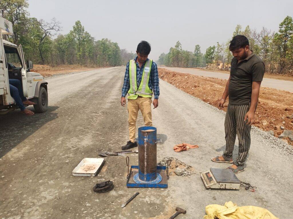
Sand Replacement Method – Field Density Test in Highway Construction
⚡ Quick Overview
- 🛠 Determines in-situ dry density of compacted soil and granular layers.
- 📏 Conducted as per IS 2720 Part 28 and MoRTH Specifications.
- 🏗 Commonly used for embankment, subgrade, GSB and WMM layers.
- ✅ Helps ensure proper compaction, pavement stability and quality control.
- 📊 Pit volume is calculated using calibrated dry sand.
Introduction
In highway and earthwork construction, proper compaction of soil layers is essential for achieving pavement strength, durability and long-term performance. Insufficient compaction can result in settlement, rutting, cracking and premature pavement failure under traffic loading.
To verify the quality of compaction achieved at site, engineers conduct field density tests. Among various field testing methods, the Sand Replacement Method is one of the most reliable and widely accepted techniques for determining the in-situ density of compacted soil and granular layers.
The method works by excavating a small pit from the compacted layer and determining its volume using calibrated dry sand of known bulk density. By comparing the field dry density with laboratory Maximum Dry Density (MDD), engineers can assess whether the required compaction has been achieved.
Importance of Field Density Test
Field density testing plays a major role in highway quality control because every pavement layer transfers traffic loads to the layer below it. Poorly compacted layers may deform under repeated loading and affect overall pavement performance.
Benefits of Proper Compaction
- Improves bearing capacity of soil
- Increases shear strength
- Reduces settlement and deformation
- Enhances pavement durability
- Minimizes permeability and moisture penetration
- Provides better resistance against traffic loading
Problems Due to Poor Compaction
- Rutting and depressions
- Differential settlement
- Surface undulations
- Cracking of pavement layers
- Reduced riding quality
- Premature pavement failure
Objective of Sand Replacement Method
The main objective of the Sand Replacement Method is to determine the in-place dry density of compacted soil or granular material and compare it with laboratory compaction values.
The test helps engineers verify:
- Whether required compaction has been achieved
- Compliance with project specifications
- Suitability of the layer for further construction
- Effectiveness of rolling operations
- Control of moisture during compaction
Principle of Sand Replacement Method
The method is based on determining the volume of a small excavated pit using dry calibration sand having known density.
The process involves:
- Excavating a pit from compacted soil
- Collecting and weighing excavated soil
- Filling the pit with calibrated sand
- Calculating pit volume from sand density
- Determining bulk density and dry density of soil
Applicable Standards and Specifications
Indian Standards
- IS 2720 Part 28 – Determination of Dry Density of Soil in Place by Sand Replacement Method
- IS 2720 Part 8 – Determination of Maximum Dry Density and Optimum Moisture Content
- IS 2720 Part 2 – Determination of Moisture Content
MoRTH Specifications
- Clause 301 – Embankment Construction
- Clause 305 – Subgrade Construction
- Clause 401 – Granular Sub-Base
- Clause 403 – Cement treated Sub-Base
- Clause 406 – Wet Mix Macadam
- Clause 601 – DLC Layers
Equipment Required
1. Sand Pouring Cylinder
A metal cylinder fitted with a conical funnel and shutter arrangement used for controlled sand flow.
2. Calibrating Container
A container of known volume used for determining bulk density of calibration sand.
3. Metal Tray with Central Hole
Used to guide excavation and sand filling operations during field density test.
4. Calibration Sand
Clean, dry, and uniformly graded sand passing through 1 mm IS sieve and retained on 600 micron sieve.
5. Weighing Balance
Used for measuring weights of sand, excavated soil, and moisture samples with accuracy up to 1 gram.
6. Excavation Tools
- Chisel
- Scraper
- Trowel
- Spoon
- Hammer
7. Moisture Containers
Used for determination of moisture content of soil samples.
Calibration of Sand
Calibration of sand is the most critical stage of the test because all field density calculations depend on the accurate determination of the bulk density of sand and cone correction factor.
Determination of Cone Correction
A certain quantity of sand remains in the conical portion of the sand pouring cylinder after each test. This quantity is known as cone correction and must be determined separately.
Procedure
- Ensure the sand pouring cylinder is clean and completely dry before use.
- Fill the cylinder with clean, dry, and uniformly graded calibration sand.
- Weigh the filled cylinder and record the initial weight (W₁).
- Place the cylinder on a smooth, level glass plate.
- Open the shutter and allow sand to flow freely under gravity.
- Allow sand to stop naturally without vibration or disturbance.
- Close the shutter after flow stops completely.
- Lift the cylinder vertically without disturbing remaining sand.
- Weigh the cylinder again and record final weight.
- Calculate cone sand weight as difference between initial and final weights.
- Repeat at least three times under identical conditions.
- Take the average value as cone correction (Wc).
Determination of Bulk Density of Sand
Bulk density of calibration sand is determined using a calibrating container of known volume.
Procedure
- Fill the sand pouring cylinder with sand and maintain constant initial weight (W₁).
- Place the cylinder over the calibrating container.
- Open the shutter and allow sand to fill the container along with cone formation.
- Close the shutter after sand flow stops completely.
- Remove the cylinder and weigh the remaining sand (W₂).
- Determine volume (V) of calibrating container using water filling method or geometric measurement.
Bulk Density of Sand
ρs = (W₁ − W₂ − Wc) / V
Where:
ρs = density of sand (g/cm³)
W₁ = initial weight of sand + cylinder
W₂ = final weight after filling container
Wc = cone correction
V = volume of calibrating container
Accurate calibration is essential because even small errors in sand density will directly affect field dry density results.
Field Test Procedure
Step 1 – Selection of Test Location
Select a representative and properly compacted location from the layer under evaluation. The selected point should reflect actual field conditions and must avoid disturbed zones, edges, or visibly loose patches.A flat area, approximately 450 rom square, of the soil to be tested shall be exposed and trimmed down to a level surface preferably with the aid of the scraper tool.
Step 2 – Surface Preparation
Clean the test area thoroughly by removing loose material, dust, and debris. Level the surface properly to ensure full contact between the metal tray and the ground without any voids or gaps.
Step 3 – Placement of Tray
Place the metal tray firmly over the prepared surface in such a way that it is stable and does not move during excavation or testing operations.
Step 4 – Excavation of Pit
Excavate a pit through the central hole of the tray using appropriate hand tools, ensuring minimal disturbance to surrounding material.
- The pit should be excavated in a regular and controlled shape
- All excavated soil must be collected without any loss
- Pit walls should remain stable and undisturbed
- No material should be left inside the pit or spilled outside
Immediately weigh the excavated wet soil to avoid moisture loss due to evaporation.
Step 5 – Determination of Moisture Content
Take a representative sample from the excavated soil for laboratory or field moisture content determination to ensure accurate dry density calculation.
Step 6 – Filling the Pit with Sand
Place the sand pouring cylinder over the tray opening and open the shutter valve carefully. Allow sand to flow into the conical funnel and excavated pit until the flow stops naturally.
Close the shutter valve and record the final weight of the cylinder.
Step 7 – Calculation of Pit Volume
Determine the weight of sand filling the pit after deducting cone correction.
Step 8 – Calculation of Bulk Density
Step 9 – Calculation of Dry Density
Percentage Compaction
The field dry density is compared with laboratory Maximum Dry Density to determine percentage compaction.
Sample Calculation
- Weight of wet excavated soil = 8.20 kg
- Moisture content = 9%
- Weight of sand filling pit = 5.00 kg
- Bulk density of sand = 1.62 g/cc
- Laboratory MDD = 2.60 g/cc
Pit Volume
Bulk Density
Dry Density
Percentage Compaction
Since the achieved compaction is below the required specification limit, re-compaction of the layer is necessary.
Acceptance Criteria
| Layer | Required Compaction | Remarks |
|---|---|---|
| Embankment | 95% – 97% MDD | As per MoRTH Clause 305 depending on embankment location and height |
| Subgrade | 97% MDD | Top subgrade layer requires strict density control |
| GSB | 98% MDD | As per MoRTH Clause 401 |
| WMM | 98% MDD | As per MoRTH Clause 406 |
| CTGSB | 98% MDD | Density should be achieved before initial cement setting |
| CTB | 98% – 100% MDD | Higher compaction improves strength and durability |
| DLC | Minimum 97% Relative Compaction | Usually checked through density/core methods |
A Practical Guide for Highway Engineers, QA/QC Professionals, and Civil Engineering Students
Common Misconception
"More roller passes mean better compaction."❌ This is not always true.
Compaction is not about running a roller repeatedly over the pavement. It is about achieving the specified field density so that the pavement can safely carry traffic loads throughout its design life.
What is Compaction?
Compaction is the process of reducing the air voids within soil, granular material, or bituminous mixes by applying mechanical energy through suitable compaction equipment such as rollers.
Proper compaction increases the density of the material, resulting in a stronger, more durable pavement structure capable of withstanding repeated traffic loading.
✅ As Air Voids Decrease
- Aggregate particles become more closely packed.
- Interlocking between particles improves.
- Load-carrying capacity increases.
- Water infiltration reduces.
- Pavement durability improves.
Primary Objective of Compaction
The primary objective of compaction is to achieve the specified density in accordance with project specifications (such as MoRTH requirements), not merely to produce a smooth-looking surface.
What Happens When Compaction is Less Than Required?
️ Practical Example
Consider a Wet Mix Macadam (WMM) layer where the project specification requires a minimum 98% Field Density. However, the Field Density Test (FDT) indicates only 95% compaction.
At first glance, the surface may appear smooth, level, and well finished. However, beneath the surface, the layer still contains excessive air voids, making it structurally weaker than intended.
What Happens Internally?
When the required density is not achieved, the aggregate particles fail to develop proper interlocking, resulting in reduced structural stability. Internally, several undesirable changes begin to occur:
- Aggregate particles remain loosely packed with excessive air voids.
- The layer compresses and settles under repeated traffic loading.
- Aggregate interlock remains weak, reducing shear resistance.
- Interconnected voids allow water to penetrate deep into the pavement.
- Moisture softens the supporting layers and accelerates deterioration.
- The pavement gradually loses stiffness and load-bearing capacity.
️ Long-Term Consequences
Inadequate compaction may not show immediate signs of distress, but over time it significantly reduces pavement performance and service life.
- Rutting develops along wheel paths due to permanent deformation.
- Fatigue cracking occurs because of repeated traffic stresses.
- Surface settlement creates uneven riding conditions.
- Water infiltration accelerates stripping and weakening of pavement layers.
- Reduced pavement service life compared to the design period.
- Increased maintenance and rehabilitation costs throughout the pavement life cycle.
Key Takeaway
A pavement can look perfectly compacted from the surface while still failing to meet density requirements internally. Only Field Density Testing (FDT) can confirm whether the specified compaction has actually been achieved.
Discussion
Every highway project presents unique challenges, and valuable lessons are often learned through practical site experience.
In your experience, what is the most common reason for failing to achieve the required field density on highway projects?
Is it due to:
- Incorrect Moisture Content (OMC)
- Excessive Layer Thickness
- Improper Roller Selection or Rolling Pattern
- Poor Quality or Improperly Graded Material
- Inadequate Number of Roller Passes
- ️ Unfavourable Weather Conditions
- Poor Site Supervision or Quality Control
- Any other practical issue you've encountered on site
Share your observations, practical experiences, and lessons learned in the comments. Your field experience can help fresh engineers, students, and fellow professionals improve their understanding of highway construction and quality control.
Let's Learn Together
Knowledge grows when professionals share real-world experiences. Whether you're a Site Engineer, QA/QC Engineer, Consultant, Contractor, or Civil Engineering Student, your insights are valuable to the engineering community.
Don't forget to share this article with your colleagues and fellow engineers if you found it useful.
💬 If you have any doubts regarding compaction, Field Density Testing (FDT), MoRTH specifications, or highway construction practices, feel free to contact me on WhatsApp. I will be happy to help.
Advantages of the Sand Replacement Method
From practical site experience, the Sand Replacement Method remains one of the most reliable techniques for checking field compaction in highway projects. It is widely used because of its accuracy, simplicity, and acceptance under MoRTH specifications.
- Reliable Field Results: Provides dependable in-situ density measurements when the test is carried out correctly.
- Ideal for Highway Layers: Suitable for embankment, subgrade, GSB, WMM, and other granular pavement layers.
- Simple Equipment: Requires basic field equipment that can be easily transported and operated at construction sites.
- Economical: Compared to advanced electronic equipment, the test is cost-effective and practical for routine quality control.
- Widely Accepted: Accepted by highway authorities, consultants, contractors, and quality control laboratories.
- Effective Quality Control Tool: Helps verify whether the specified compaction has actually been achieved before allowing the next construction activity.
Limitations of the Sand Replacement Method
Although the method is highly reliable, every site engineer should understand its practical limitations before selecting it for field testing.
- Not Suitable for Saturated Soils: High moisture conditions may affect excavation and density determination.
- Difficult in Large Aggregate Layers: Excavating a uniform pit becomes difficult where oversized aggregates are present.
- Calibration is Critical: Incorrect calibration of standard sand directly affects the accuracy of the test.
- Time-Consuming: The complete testing process requires more time than nuclear density gauges or other modern equipment.
- Operator Dependent: Test accuracy largely depends on the experience and care of the field engineer conducting the test.
Common Mistakes Observed on Construction Sites
During highway projects, many Field Density Tests fail not because of poor compaction but because of incorrect testing practices. The following mistakes are frequently observed on site:
- Improper Sand Calibration: Using incorrectly calibrated sand results in an incorrect pit volume, leading to inaccurate field density calculations.
- Loss of Excavated Soil: Soil falling outside the collection tray or remaining inside the pit reduces the measured weight and produces incorrect density values.
- Irregular Excavation: A pit with uneven sides or excessive depth affects the calculated volume and reduces test reliability.
- Using Moist Calibration Sand: Damp sand changes its bulk density and flow characteristics, causing significant measurement errors.
- Incorrect Moisture Content Measurement: Errors during moisture determination directly affect the calculated dry density.
- Testing Disturbed Areas: Never perform FDT on loose, repaired, or disturbed locations that do not represent actual field compaction.
- Improper Seating of the Base Plate: Any gap between the tray and the compacted surface allows sand leakage and produces an incorrect pit volume.
- Delay in Moisture Testing: If the excavated sample is left exposed for a long time, moisture evaporates, resulting in incorrect dry density calculations.
Importance in Highway Quality Control
As a site engineer, the Field Density Test is not merely a contractual requirement—it is one of the most important quality control activities carried out during construction. A pavement layer should never be accepted based solely on its appearance; acceptance must always be supported by satisfactory field density results.
- Verifies Proper Compaction: Confirms that the compacted layer has achieved the required percentage of Maximum Dry Density (MDD).
- Ensures Compliance with MoRTH Specifications: Provides documentary evidence that the work satisfies project quality requirements.
- Improves Structural Performance: Properly compacted layers distribute traffic loads efficiently and reduce structural distress.
- Increases Pavement Life: Good compaction minimizes settlement, rutting, cracking, and moisture-related failures.
- Reduces Future Maintenance: Well-compacted pavement layers require fewer repairs and lower maintenance expenditure.
- Supports Layer Approval: Field Density Test results form the basis for approving subsequent construction activities.
Safety Precautions During Testing
- Wear reflective jackets, safety shoes, gloves, and other required PPE.
- Place warning signs or traffic cones when testing on active carriageways.
- Handle excavation tools carefully to avoid injuries.
- Avoid testing during heavy rainfall or when the surface is excessively wet.
- Protect excavated samples from contamination and moisture loss.
- Maintain proper housekeeping around the test location to avoid accidents.
Practical Recommendations from Site Experience
- Perform FDT Immediately After Final Rolling: Testing should be completed before the layer loses moisture or becomes disturbed by construction traffic.
- Select Representative Test Locations: Avoid choosing only visually good locations. Test points should fairly represent the entire work area.
- Avoid Edge Areas: Compaction near pavement edges and shoulders is generally less uniform and should only be tested if specifically required.
- Maintain Calibration Records: Regularly verify the calibration of standard sand, pouring cylinder, and cone correction values.
- Maintain Moisture Close to OMC: Compaction near Optimum Moisture Content provides the best opportunity to achieve Maximum Dry Density.
- Follow Specified Testing Frequency: Always comply with the frequency specified in MoRTH, project specifications, or the Quality Assurance Plan (QAP).
- Inspect Equipment Before Every Test: Ensure the sand pouring cylinder, tray, balance, and accessories are clean, dry, and functioning correctly.
- Never Accept Work Without Verification: A smooth-looking surface is not proof of proper compaction. Acceptance should always be based on verified Field Density Test results.
Conclusion
The Sand Replacement Method (Field Density Test) remains one of the most reliable and widely accepted methods for determining the in-situ dry density of compacted soil and granular layers in highway construction. When performed correctly, it provides accurate confirmation that the specified compaction requirements have been achieved before the next layer is placed.
From a site engineer's perspective, the Field Density Test is far more than a routine quality control activity. It is a critical acceptance test that verifies whether the compacted layer complies with MoRTH, IS Specifications, and project requirements. Proper testing, accurate calibration, representative sampling, and correct moisture determination help prevent settlement, rutting, premature pavement failures, and costly rework.
Remember: A pavement may appear smooth and well-compacted, but appearance alone cannot confirm adequate compaction. Only a properly conducted Field Density Test (FDT) can verify that the required engineering standards have been achieved.
❗ Use only clean, dry, and free-flowing calibration sand.
❗ Verify sand calibration and cone correction before testing.
❗ Prevent vibration or movement while sand is flowing into the pit.
❗ Collect the entire excavated soil sample without any loss.
❗ Determine moisture content immediately to avoid moisture loss.
❗ Repeat the test if abnormal or inconsistent results are obtained.
❗ Never approve a pavement layer without confirming the required field density.
Complete Field Density Testing Excel Toolkit
Everything you need for Field Density Testing in one professional Excel package. Save time with ready-to-use formats featuring automatic calculations, laboratory-ready reports, and instant download.
📦 Included Excel Formats
- ✔ Sand Replacement Method
- ✔ Core Cutter Method
- ✔ Sand Pouring Cylinder Calibration
- ✔ Rapid Moisture Meter (RMM) Calibration
- ✔ Automatic Calculations
- ✔ Ready-to-use Observation Sheets
- ✔ Professional Laboratory Report Format
- ✔ Print Ready (A4 Size)
- ✔ Editable Excel (.xlsx)
- ✔ Instant Download
- ✔ Lifetime Access
👷 Perfect For
- Highway Engineers
- Civil Engineers
- QA/QC Engineers
- Material Testing Laboratories
- Consultants
- EPC Contractors
- Engineering Students
🔥 Save ₹97
✔ Sand Replacement Method | ✔ Core Cutter Method | ✔ Sand Pouring Cylinder Calibration | ✔ RMM Calibration
Or Buy Individually
✔ Secure Payment | ✔ Instant Download | ✔ Lifetime Access
```