HIGHWAY QUALITY TEST

Precision Testing. Proven Quality. Safer Infrastructure.

Plastic Limit of Soil

Plastic Limit of Soil Test (PL Test) – Procedure & Calculations Plastic Limit of Soil Test (PL Test) The Plastic Limit of Soil (PL) is defined as the moisture content at which a fine‑grained soil begins to exhibit plastic behavior — it can be deformed without cracking or crumbling. Determining the PL is a key part of soil classification and geotechnical evaluation for engineering works. The outcome of the PL Test is used to compute important indices like Plasticity Index (PI), Liquidity Index (LI), and Consistency Index (CI), which help engineers predict settlement potential, shrink-swell behavior, and workability during construction. This test is part of a suite of soil evaluations. For example, the Liquid Limit of Soil test complements the PL Test by identifying when soil transforms to a liquid state. The Modified Proctor Compaction Test determines optimum moisture content and maximum dry density, and the CBR Test evaluates soil bearing capacity for pavement design. Introduction Fine-grained soils such as silts and clays change behavior depending on water content. These behaviors are categorized under Atterberg limits: Liquid Limit (LL): Water content at which soil behaves like a liquid. Plastic Limit (PL): Water content at which soil exhibits plasticity. Shrinkage Limit (SL): Water content at which further drying does not result in volume change. The Plastic Limit is considered the lower bound of the plastic state. Soils with higher PL tend to be more cohesive and resist deformation. Accurate PL determination is essential for earthwork design, foundation engineering, and soil suitability assessment in pavement and structural applications. Objective of Plastic Limit Test To determine the Plastic Limit (PL) as per IS standards. To classify soils based on plasticity characteristics. To calculate key soil indices like PI, LI, and CI. To assess soil workability, compaction behavior, and moisture sensitivity. Apparatus Required Evaporating dish for collecting crumbled soil. Spatula and mixing tray. Glass plate for rolling soil threads. Moisture containers with lids for storing samples. Rolling rod (3 mm diameter) for thread rolling. Sensitive balance with accuracy of 0.01 g. Oven maintained at 105–110 °C for moisture determination. Sample Preparation Collect soil passing through a 425 μm IS sieve for fine-grained behavior. Air-dry and break down clumps for uniformity. Take 20–25 g of soil for testing. Add distilled water gradually to form a uniform plastic paste. Mix thoroughly and allow brief equilibrium. Procedure for Plastic Limit Test Sl. No. 1: About 20 g of dry pulverized soil passing 425 micron IS sieve is weighed. The soil is mixed thoroughly with distilled water in the evaporating dish till the soil paste is plastic enough to be easily moulded with fingers. Sl. No. 2: A small ball is formed with the fingers and this is rolled between the fingers and glass plate to a thread. The pressure just sufficient to roll into a thread of uniform diameter should be used. Sl. No. 3: The rate of rolling should be between 80 to 90 strokes per minute, counting a stroke as one complete motion of hand forward and back to the starting position again. Sl. No. 4: The rolling is done till the diameter of the thread is 3 mm. Then the soil is kneaded together to a ball and rolled again to form thread. Sl. No. 5: This process of alternate rolling and kneading is continued until the thread crumbles under pressure required for rolling and the soil can no longer be rolled into a thread. Sl. No. 6: If the crumbling starts at diameter less than 3 mm, then moisture content is more than plastic limit and if the diameter is greater while crumbling starts, the moisture content is lower. Sl. No. 7: By trial, the thread that starts crumbling at 3 mm diameter under normal rolling should be obtained and this should be immediately transferred to the moisture container, lid placed over it and weighed. Sl. No. 8: The container is kept in the oven for about a day and dry weight found to determine the moisture content of the thread. Sl. No. 9: The above process is repeated to get at least three consistent values of the plastic limit (PL or WP). Calculations Plasticity Index (PI) PI = Liquid Limit (LL) – Plastic Limit (PL) PI = WL – WP Liquidity Index (LI) LI = (W – WP) / PI Where W = natural moisture content Consistency Index (CI) CI = (WP – W) / PI Toughness Index (TI) TI = PI / IF Where IF = Flow index from Liquid Limit Test Factors Affecting Plastic Limit Soil mineralogy (montmorillonite, kaolinite, etc.) Organic content — higher retention increases PL Sample preparation — inconsistent moisture affects results Rolling technique — uniform pressure improves accuracy Engineering Applications Soil Classification: PL is key for Atterberg limit-based classification. Pavement Subgrades: PL helps identify moisture-sensitive soils. Compaction Control: Guides optimum moisture for target densities. Foundation Behavior: Indicates compressibility and shrink-swell potential. Acceptance Criteria for Construction Soil Type Plastic Limit (PL %) Plasticity Index (PI) Suitability Granular Subgrade > 15 < 10 Suitable Clayey Subgrade 15–25 10–30 Conditional Highly Plastic Clay > 25 > 30 Unsuitable Precautions and Tips Use freshly prepared soil paste. Maintain uniform rolling pressure and speed. Determine moisture immediately after crumbling. Conduct multiple trials for accurate results. Conclusion The Plastic Limit of Soil is an essential measure of plastic behavior in fine-grained soils. Combined with Liquid Limit, Modified Proctor Compaction, and CBR Test, engineers can fully evaluate soil performance for highways, foundations, and earthworks. Accurate PL determination ensures better design, compaction control, and soil suitability assessment. ([highwayqualitytest.com](https://highwayqualitytest.com/modified-proctor-test/?utm_source=chatgpt.com)) HIGHWAY QUALITY TEST Download Atterberg Limits Test Excel Format Prepare professional Atterberg Limits Test reports in minutes using our ready-to-use Excel format with automatic calculations. Determine the Liquid Limit (LL), Plastic Limit (PL), and Plasticity Index (PI) accurately while eliminating manual calculation errors. 💰 Only ₹99 One-Time Payment • Instant Access • Lifetime Access 🛒 Buy Atterberg Limits Excel Format ✔ Secure Payment   |   ✔ Instant Download   |   ✔ Editable Excel

Plastic Limit of Soil Read More »

Soil

Earthwork Quantity Calculation (Step-by-Step Guide)

Earthwork Quantity Calculation (Step-by-Step Guide) | Highway Quality Test Part 9 – Earthwork Quantity Calculation (Step-by-Step Guide) | Every Civil Engineer Should Know Earthwork quantity calculation is one of the most important activities in civil and highway engineering. Whether you’re constructing a road embankment, highway cutting, canal, railway formation, or site development project, accurate earthwork estimation is essential for preparing Bills of Quantities (BOQs), planning equipment, estimating project costs, scheduling construction activities, and verifying contractor bills. In highway projects, even a small error in earthwork estimation can result in significant cost overruns, material shortages, and project delays. Therefore, every Civil Engineer, Highway Engineer, Site Engineer, QA/QC Engineer, Quantity Surveyor, Consultant, and Contractor should understand how to calculate earthwork quantity accurately. This practical guide explains the complete earthwork quantity calculation process using simple formulas, solved examples, engineering principles, and practical site tips. Figure 1. Step-by-step earthwork quantity calculation for a highway embankment. Table of Contents Why Earthwork Quantity Calculation is Important Earthwork Quantity Formula Step-by-Step Example Quick Thumb Rule Engineering Perspective Methods of Earthwork Calculation Practical Tips Common Mistakes Frequently Asked Questions Conclusion Why is Earthwork Quantity Calculation Important? Earthwork estimation forms the foundation of every infrastructure project. Accurate quantity calculation helps engineers estimate excavation and embankment volumes, plan equipment deployment, prepare contractor bills, optimize project costs, and ensure efficient material management. Proper earthwork quantity calculation also supports project planning by minimizing material wastage, improving productivity, and ensuring compliance with approved drawings and project specifications. Prepare accurate BOQs. Estimate excavation and embankment quantities. Plan manpower and machinery. Estimate transportation requirements. Control project cost. Prepare contractor bills. Reduce construction delays. Improve construction planning. Earthwork Quantity Formula Earthwork quantity is the total volume of soil required for excavation or embankment construction. It is generally measured in cubic metres (m³). For a simple rectangular section, the quantity is calculated by multiplying the cross-sectional area by the length of the work. Standard Formula Earthwork Quantity (m³) = Cross-Sectional Area × Length For a Rectangular Section: Earthwork Quantity = Length × Width × Height This formula is suitable for simple embankments, trenches, and excavations having a uniform rectangular cross-section. Data Required for Earthwork Quantity Calculation Before performing the calculation, collect the following information from the approved drawings and survey records. Parameter Unit Description Length m Total length of embankment or excavation Formation Width m Finished formation width Height / Depth m Compacted embankment height or excavation depth Side Slopes Ratio If applicable for embankments or cuttings Ground Levels m Existing Ground Level (EGL) and Finished Road Level (FRL) Step-by-Step Earthwork Quantity Calculation Let’s calculate the earthwork quantity using a practical highway embankment example. Given Data Item Value Embankment Length 100 m Formation Width 10.0 m Compacted Height 1.50 m Step 1 – Calculate the Cross-Sectional Area Use the following formula: Cross-Sectional Area = Width × Height = 10 × 1.5 = 15.00 m² Therefore, the cross-sectional area of the embankment is 15.00 m². Step 2 – Calculate Earthwork Quantity Multiply the cross-sectional area by the total length. Earthwork Quantity = Cross-Sectional Area × Length = 15 × 100 = 1,500 m³ Final Answer A highway embankment having a length of 100 metres, a formation width of 10 metres, and a compacted height of 1.5 metres requires approximately 1,500 cubic metres (m³) of compacted earthwork. Quick Thumb Rule For quick site calculations where the cross-section is rectangular, use the following thumb rule. Earthwork Quantity (m³) Length × Width × Height Example: Length Width Height Quantity 100 m 10 m 1.5 m 1,500 m³ This thumb rule is ideal for preliminary estimates during planning and site execution. For actual project billing, always use approved survey data and detailed cross-sections. Engineering Perspective In real highway and infrastructure projects, earthwork quantity is influenced by several engineering parameters. The simple rectangular formula is suitable only for uniform sections. Actual embankment and cutting quantities often require additional considerations. Formation width Embankment or cutting height Side slopes Existing ground profile Finished Road Level (FRL) Existing Ground Level (EGL) Shrinkage and bulking factors Compaction requirements Approved project specifications Professional Tip: For highway embankments, the cross-sectional area generally includes side slopes. Quantities should be calculated using approved cross-sections, and methods such as the Average End Area Method or the Prismoidal Formula should be adopted for irregular terrain to achieve higher accuracy. Methods of Earthwork Quantity Calculation The method adopted for earthwork quantity calculation depends on the project type, ground profile, and the required level of accuracy. In highway projects, the following methods are commonly used. Method Application Accuracy Cross-Section Method Simple embankments and excavations Good Average End Area Method Highway and railway projects Very Good Prismoidal Formula Irregular terrain and detailed estimation Excellent Digital Terrain Model (DTM) Large infrastructure projects using survey software Excellent Average End Area Method Volume = (A₁ + A₂) / 2 × Length Where: A₁ = Area of First Cross-Section A₂ = Area of Second Cross-Section Length = Distance between Cross-Sections This method is widely used for highway embankments because it provides reliable results when the ground profile changes gradually. Practical Tips for Site Engineers ✔ Always use dimensions from approved drawings and survey records. ✔ Verify Existing Ground Level (EGL) before starting calculations. ✔ Check Finished Road Level (FRL) from approved GAD or longitudinal section. ✔ Convert all dimensions into metres. ✔ Calculate earthwork in cubic metres (m³). ✔ Consider side slopes for embankment and cutting sections. ✔ Include shrinkage, bulking, and compaction factors wherever applicable. ✔ Cross-check quantities with Total Station or survey data. ✔ Verify calculations before preparing contractor bills. ✔ Follow project specifications and approved drawings for final measurements. Common Mistakes to Avoid Many quantity estimation errors occur due to incorrect assumptions or improper measurements. Avoid the following common mistakes: ❌ Ignoring side slopes while calculating embankment quantity. ❌ Using loose fill dimensions instead of compacted dimensions. ❌ Mixing millimetres and metres in calculations. ❌ Ignoring survey data and relying only on approximate measurements. ❌ Not considering shrinkage or bulking factors. ❌ Using design levels instead

Earthwork Quantity Calculation (Step-by-Step Guide) Read More »

Uncategorized

METHOD STATEMENT FOR OPEN FOUNDATION

Method Statement for Open Foundation 1. Description This Method Statement covers the construction of Plain Cement Concrete (PCC) and Reinforced Cement Concrete (RCC) Open Foundations in accordance with the approved drawings, contract specifications, and the MoRTH Specifications for Road and Bridge Works. The scope of work includes survey and setting out, excavation, preparation of the foundation bed, dewatering (where required), laying of PCC, reinforcement fixing, formwork, concreting, curing, quality control, safety requirements, and backfilling after completion of foundation works. 2. Materials All materials used for the construction of the open foundation shall conform to Section 1000 of the MoRTH Specifications, relevant Indian Standards (IS Codes), approved mix designs, and the requirements of the Contract. Only approved materials accompanied by valid test certificates and accepted by the Engineer shall be used for the work. Materials shall be properly stored, handled, and protected from contamination or deterioration prior to use. Cement conforming to the relevant IS Specifications. Fine Aggregate conforming to IS 383 and MoRTH requirements. Coarse Aggregate conforming to IS 383 and MoRTH requirements. Reinforcement Steel conforming to IS 1786 and approved Bar Bending Schedule (BBS). Water suitable for concrete production and curing in accordance with IS 456. Approved chemical admixtures, if specified in the approved mix design. Formwork materials capable of maintaining the required line, level, dimensions, and finish. Quality Requirement: All construction materials shall be inspected, tested, and approved before use. Material test reports shall be maintained as part of the project Quality Assurance/Quality Control (QA/QC) documentation. 3. Preparation of Foundations Excavation for laying the foundation shall be carried out in accordance with MoRTH Clause 300 and the approved drawings. The excavation shall be taken to the required line, level, dimensions, and founding level specified in the drawings. Open foundations shall preferably be constructed under dry conditions. Where groundwater or seepage is encountered, suitable dewatering arrangements such as pumping, well-point systems, or diversion channels shall be provided and maintained throughout the construction period to ensure a clean, stable, and workable foundation bed. The excavation bed shall be cleaned of all loose, soft, organic, and unsuitable materials before inspection by the Engineer. No concrete shall be placed until the foundation bed has been inspected and approved. 4. Setting Out The foundation layout shall be established in accordance with the approved General Arrangement (GA) drawings and survey control points. The plan dimensions of the foundation shall be set out at the bottom of the excavation using a Total Station, Auto Level, and measuring tape. The layout shall be checked with respect to the original centre line, reference benchmarks, and structural axes to ensure dimensional accuracy. It shall be ensured that no portion of the bearing surface is higher than the approved founding level indicated on the drawings. All survey checks shall be verified and approved by the Engineer before commencement of PCC works. 5. Safe Bearing Capacity (SBC) of Soil The Safe Bearing Capacity (SBC) of the foundation soil shall be verified at the founding level in accordance with the approved drawings, geotechnical investigation report, and project specifications. Where specified in the Contract, the SBC shall be confirmed by the in-house Quality Control (QC) Laboratory or an approved testing agency before commencement of foundation works. Test results shall be reviewed and approved by the Engineer prior to placing Plain Cement Concrete (PCC). If the actual soil conditions or Safe Bearing Capacity are found to differ from the design assumptions, the matter shall be immediately reported to the Engineer for further investigation and approval before proceeding with the work. 6. Construction of Open Foundation Construction of the open foundation shall be carried out in accordance with the approved drawings, relevant MoRTH Specifications, and the approved Method Statement. The foundation bed shall be inspected and approved by the Engineer before commencement of concrete works. Where the bearing surface consists of natural earth, a 150 mm thick Plain Cement Concrete (PCC) layer of Grade M15 shall be laid below the structural foundation concrete unless otherwise specified in the drawings or Contract. The lean concrete shall provide a clean, level, and stable working surface for reinforcement fixing and formwork erection. Generally, no side formwork is required for the lean concrete layer. However, where necessary to maintain dimensions or due to unstable excavation sides, suitable formwork may be provided with the approval of the Engineer. Side formwork shall be provided for the structural foundation concrete to maintain the required dimensions, alignment, and surface finish. Top formwork shall also be provided where the slope of the concrete surface is steeper than 1 Vertical : 3 Horizontal (1V:3H) to prevent displacement or slippage of freshly placed concrete. Where concrete is placed on sloping surfaces without top formwork, the concrete slump shall be carefully controlled to ensure adequate workability while preventing segregation or movement of fresh concrete. The concrete shall be placed in a continuous operation and compacted using approved mechanical vibrators. In cases involving steeply sloping surfaces, the top formwork may be erected progressively as concreting advances to ensure proper compaction and dimensional accuracy. Reinforcement shall be fabricated, fixed, and supported strictly in accordance with the approved structural drawings, Bar Bending Schedule (BBS), IRC:112, and MoRTH Specifications. The specified clear cover shall be maintained throughout the concreting operation using approved concrete cover blocks. Before placing the lean concrete, the foundation bed shall be thoroughly cleaned of all loose soil, organic matter, standing water, and other deleterious materials. The surface shall be lightly moistened to prevent excessive absorption of water from the concrete. Care shall be taken to avoid muddy conditions. Any softened or disturbed portion of the foundation bed resulting from over-wetting or other causes shall be removed, re-compacted where necessary, and brought back to the required level before concrete placement. Quality Control: Lean concrete and foundation concrete shall not be placed until the excavation, founding level, reinforcement, formwork, and foundation bed have been inspected and approved by the Engineer. 7. Inspection Plan and Testing S. No. Construction Activity Inspection Required Testing / Verification Required Remarks 1


METHOD STATEMENT FOR OPEN FOUNDATION Read More »

Concrete Work

Clearing and Grubbing Methodology as per MoRTH Clause 201

Clearing and Grubbing is the first activity before earthworks. It covers removal and disposal of vegetation including trees (up to 300 mm girth), bushes, shrubs, stumps, roots, grass, weeds, rubbish and top organic soil up to 150 mm thick. The scope includes draining stagnant water, backfilling pits created by uprooting trees and compacting to required density as per MoRTH Clause 305.3.4.

Clearing and Grubbing Methodology as per MoRTH Clause 201 Read More »

Earthwork
flakiness and elongation guage

Flakiness & Elongation Test

Flakiness & Elongation Index Test – Method Statement Flakiness & Elongation Index Test – IS 2386 Procedure with Calculation Procedure • Apparatus • IS Sieve Table • Results format OBJECT Assess aggregate particle shape quality using the Flakiness & Elongation Index Test as per IS 2386 (Part I). This essential aggregate shape test determines the percentage of flaky and elongated particles that can adversely affect compaction, interlocking, and overall pavement performance. Excessive flaky and elongated aggregates reduce load-bearing capacity, increase voids, and lead to premature failures such as rutting, cracking, and surface deformation in flexible pavements. Therefore, strict compliance with IS specifications is critical for ensuring structural durability and long service life. This practical, site-ready guide covers: Required apparatus and gauge dimensions Step-by-step laboratory procedure Calculation formulas for Flakiness Index (FI) and Elongation Index (EI) Permissible limits as per MoRTH and IS standards Interpretation tips for QA/QC engineers Designed specifically for site engineers, QA/QC teams, and highway professionals, this guide ensures accurate testing, proper documentation, and informed decision-making for high-performance pavement construction. APPARATUS The apparatus for the shape tests consists of the following: A standard thickness gauge A standard length gauge IS sieves of sizes: 63, 50, 40, 31.5, 25, 20, 16, 12.5, 10 and 6.3 mm A balance of capacity 5 kg, readable and accurate up to 1 g The particle shape of aggregates is determined by the percentages of flaky and elongated particles contained in it. For base course and construction of bituminous and cement concrete types, the presence of flaky and elongated particles are considered undesirable as these cause inherent weakness with possibilities of breaking down under heavy loads. Thus, evaluation of shape of the particles, particularly with reference to flakiness and elongation is necessary. The Flakiness Index of aggregates is the percentage by weight of particles whose least dimension (thickness) is less than three-fifths (0.6 times) of their mean dimension. This test is not applicable to sizes smaller than 6.3 mm. The Elongation Index of an aggregate is the percentage by weight of particles whose greatest dimension (length) is greater than nine-fifths (1.8 times) their mean dimension. This test is also not applicable for sizes smaller than 6.3 mm. PROCEDURE Sieve the sample through the IS sieves (as specified in the table). Take a minimum of 200 pieces of each fraction to be tested and weigh them or take the maximum number of pieces available up to 200 Nos. In order to separate the flaky materials, gauge each fraction for thickness on a thickness gauge. The width of the slot used should be of the dimensions specified in column (4) of the table for the appropriate size of the material. Weigh the flaky material passing the gauge to an accuracy of at least 0.1 per cent of the test sample. In order to separate the elongated materials, gauge the non-flaky material for length on a length gauge. The width of the slot used should be of the dimensions specified in column (6) of the table for the appropriate size of the material. Weigh the elongated material retained on the gauge to an accuracy of at least 0.1 per cent of the test sample. IS SIEVE & GAUGE TABLE Passing through IS Sieve, mm Retained on IS Sieve, mm Weight of fraction (200 pieces), g Thickness gauge size, mm Weight passing thickness gauge (Xi) Length gauge size, mm Weight retained on length gauge (Yi) 63 50 W1 23.90 X1 – – 50 40 W2 27.00 X2 81.00 Y1 40 31.5 W3 19.50 X3 58.00 Y2 31.5 25 W4 16.95 X4 – – 25 20 W5 13.50 X5 40.5 Y3 20 16 W6 10.80 X6 32.4 Y4 16 12.5 W7 8.55 X7 25.5 Y5 12.5 10 W8 6.75 X8 20.2 Y6 10 6.3 W9 4.89 X9 14.7 Y7 Total W = X = Y = OBSERVATIONS and: FORMULAE Record every fraction’s weights clearly. Use at least two significant figures for percentages and record sample piece counts. Flakiness Index = ((X1 + X2 + …) / (W1 + W2 + …)) × 100 Elongation Index = ((Y1 + Y2 + …) / (W1 + W2 + …)) × 100 Fraction Total pieces taken (Wi) Flaky weight (Xi) Elongated weight (Yi) Remarks 63–50 mm 50–40 mm 40–31.5 mm 31.5–25 mm 25–20 mm 20–16 mm 16–12.5 mm 12.5–10 mm 10–6.3 mm Total RESULT I. Flakiness Index = X II. Elongation Index = Y NOTES & REFERENCES This document preserves the original technical content. Do not alter the definitions if your contract specification references a specific IS edition. Reference: IS 2386 Part 1 – Methods of Test for Aggregates for Concrete (Particle Shape Tests). Record environmental conditions and the balance calibration status with every test batch for traceability. Permissible Limits as per MoRTH Application Combined FI + EI Limit Bituminous Concrete (BC) ≤ 30% Dense Bituminous Macadam (DBM) ≤ 35% Wet Mix Macadam (WMM) ≤ 35% Note: Always verify latest MoRTH revision applicable to your contract. Document: • Generated: 20 Nov 2025 Enter Values to Calculate Indices W Values X Values Y Values Calculate Results: Flakiness Index: 0% Elongation Index: 0% Quick Reference: Flakiness & Elongation Index Test Applicable Aggregate Size: Only aggregates ≥6.3 mm are tested. Minimum Sample Count: 200 pieces per sieve fraction (or maximum available). Flakiness Index Criterion: Particles with thickness < 0.6 × mean size. Elongation Index Criterion: Particles with length > 1.8 × mean size. Required Gauges: Thickness gauge for flakiness; Length gauge for elongation. Accuracy: Weigh materials to at least 0.1% accuracy of sample weight. Outcome: FI = (Flaky Weight / Total Weight) × 100; EI = (Elongated Weight / Total Weight) × 100. Purpose: Ensures aggregates are suitable for pavement and concrete strength requirements. Top FAQs – Flakiness & Elongation Index Test What is the minimum aggregate size for these tests? Aggregates smaller than 6.3 mm are not tested. Why are flaky and elongated particles undesirable? They reduce pavement strength and break easily under heavy loads. How many aggregate pieces must be tested? A

Flakiness & Elongation Test Read More »

Aggregate
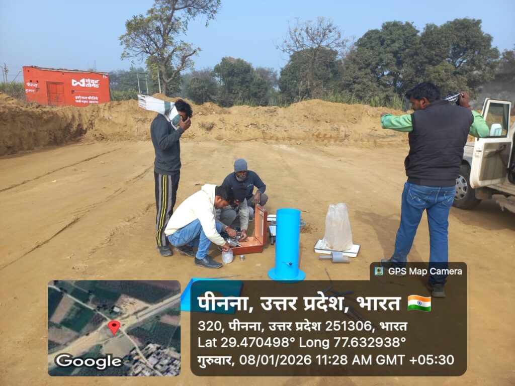
Sand Replacement Method | Field Density Test of Soil (IS 2720)

Sand Replacement Method | Field Density Test of Soil (IS 2720)

Pavement performance begins long before traffic opens. It starts with compaction quality. Field Density Test (FDT) is the backbone of compaction control in highway construction, ensuring that each layer achieves the density required for long-term performance.

Without proper field density, even the best materials and designs can fail prematurely.

Sand Replacement Method | Field Density Test of Soil (IS 2720) Read More »

Granular Work

© 2026 HIGHWAY QUALITY TEST. All rights reserved.

WhatsAppNeed Help?
Scroll to Top