PQC Methodology
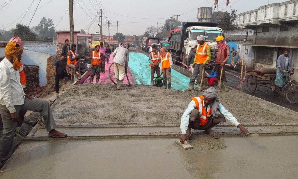
Pavement Quality Concrete (PQC) M40 – Complete Construction & QA/QC Guide Pavement Quality Concrete (PQC) M40: Complete Construction & QA/QC Guide 1. General Overview Pavement Quality Concrete (PQC) is the final structural layer of rigid pavement designed to directly carry traffic loads and distribute them safely to underlying layers. It is a high-strength cement concrete layer constructed over DLC/WMM/GSB as per approved drawings and MoRTH specifications. The success of PQC depends on strict control of: Sub-base readiness (DLC/WMM quality) Concrete mix design and production control Continuous paving without interruption Proper vibration, finishing, and leveling Joint construction and curing discipline Applicable Standards Reference Documents S. No. Document Description 1 Contract Agreement 2 IRC: SP: 84-2014 3 Ministry of Road Transport & Highways Specifications (MoRTH – 5th Revision) 4 Relevant Drawings 2. Pre-Construction Requirements Pavement Quality Concrete (PQC) shall be executed only after ensuring that all pre-construction conditions are satisfied as per MoRTH and approved project specifications. 2.1 Base Layer Approval (DLC / GSB) PQC shall not be laid until the underlying layer is fully approved by the Engineer. Formation / DLC / GSB must be properly compacted Surface shall be true to line, level, and cross fall Free from loose soil, dust, and contamination Field Density Test (FDT) results must be approved Surface shall be thoroughly cleaned before PQC laying Strong Base = Long Life Pavement. Any weakness in DLC/GSB directly affects PQC performance. 2.2 Plant & Equipment Approval The following equipment must be deployed, tested, and approved before PQC execution: Fully calibrated concrete batching plant Transit mixers / dumpers in adequate quantity Needle vibrators (minimum 2 per paving team) Screed vibrator / slip form paving machine (sensor paver preferred) Water tanker for curing operations 3 m straight edge and leveling instruments Concrete saw cutting machine for joint cutting 3. Survey, Setting Out & String Line Control Accurate survey control is essential for achieving correct alignment, level, and riding quality of PQC pavement. 3.1 Control Points Center line established using Total Station Edge lines marked as per approved drawings Formation levels transferred from GFC drawings Benchmarks shall be protected throughout construction 3.2 Level Control System String line system used for fixed form paving Automatic sensor control system used for slip form paving Level pegs installed at specified intervals 👉 Even a small level deviation at this stage directly affects pavement smoothness and riding quality. 4. Concrete Mix Design & Production 4.1 Mix Design Requirements Concrete mix shall be designed as per approved design mix (generally M40/M35 or as specified in contract). Design as per IS 10262 and MoRTH Clause 602 Minimum cement content as per specification requirements Strict control of water-cement ratio Use of approved admixtures for workability and setting control 4.2 Batching Plant Operations Batching plant shall be fully calibrated before start of work Moisture correction in aggregates is mandatory daily Weigh batching system only (volume batching strictly prohibited) Uniform mixing time shall be maintained for every batch Mix consistency shall be checked regularly Consistent batching = Consistent strength. Any variation in batching directly affects flexural strength of PQC. 5. Transportation of Concrete Concrete shall be transported using transit mixers only Segregation of concrete during transport shall be strictly avoided No delay beyond initial setting time is permitted Concrete shall be discharged immediately at site Site Slump Control Slump shall be checked at site for every batch Typical range: 30 – 60 mm (as per design requirement) No water shall be added at site without Engineer approval Any delay or re-tempering of concrete at site will lead to rejection of the batch. 6. Laying of PQC (Execution Control: From QA/QC point of view, PQC laying is not just a construction activity but a controlled engineering process where time, vibration, placement, and finishing directly govern the structural performance and service life of the pavement. Strict supervision, continuous monitoring, and zero-tolerance control are required during this stage. 6.1 Placement Control : Concrete placement shall be executed in a continuous and uninterrupted operation to ensure structural integrity of PQC slabs. Placement shall be continuous without stoppage under normal conditions Cold joints are strictly prohibited in PQC construction Concrete shall not be rehandled, remixed, or re-tempered at site Concrete shall be discharged ahead of the paving machine in a controlled and uniform manner From QA/QC perspective: Any interruption in placement leads to weak planes, reduced load transfer efficiency, and early pavement distress. 6.2 Compaction Control (Critical QA/QC Activity) Compaction is the most sensitive operation in PQC construction and must be strictly monitored by QA/QC engineers during execution. Internal needle vibrators shall be used uniformly across the full slab width Vibration pattern shall follow systematic overlapping to avoid un-compacted zones Vibrators shall be inserted vertically and withdrawn slowly to ensure full densification Over-vibration must be strictly avoided to prevent segregation and bleeding of cement slurry 👉 QA/QC Insight: Proper compaction ensures homogeneous density, high flexural strength, and long-term pavement durability. Improper vibration is a primary cause of honeycombing and premature failures. 6.3 Finishing Control (Surface Quality Requirement) Finishing operations directly define the riding quality, skid resistance, and service performance of the pavement and therefore require strict QA/QC supervision. Screeding shall be carried out immediately after completion of compaction Surface shall be finished to required line, level, and cross fall as per drawings Floating shall be done to achieve uniform surface texture and smoothness Edge correction shall be carried out manually wherever required with full control From HOP perspective: Final finishing determines client acceptance. Even minor surface irregularities can lead to rejection or grinding requirement. 7. Surface Texturing Surface texturing in Pavement Quality Concrete (PQC) is a critical finishing operation carried out to ensure adequate skid resistance, safe vehicular movement, and long-term riding performance of the pavement surface. From a QA/QC and Head of Project perspective, texturing is directly linked with road safety, surface performance, and client acceptance. 7.1 Purpose of Surface Texturing To provide adequate skid resistance for moving traffic To improve braking performance and safety under wet conditions To ensure uniform surface roughness