HIGHWAY QUALITY TEST

Precision Testing. Proven Quality. Safer Infrastructure.

Kishor Kumar

Plastic Limit of Soil

Plastic Limit of Soil Test (PL Test) – Procedure & Calculations Plastic Limit of Soil Test (PL Test) The Plastic Limit of Soil (PL) is defined as the moisture content at which a fine‑grained soil begins to exhibit plastic behavior — it can be deformed without cracking or crumbling. Determining the PL is a key part of soil classification and geotechnical evaluation for engineering works. The outcome of the PL Test is used to compute important indices like Plasticity Index (PI), Liquidity Index (LI), and Consistency Index (CI), which help engineers predict settlement potential, shrink-swell behavior, and workability during construction. This test is part of a suite of soil evaluations. For example, the Liquid Limit of Soil test complements the PL Test by identifying when soil transforms to a liquid state. The Modified Proctor Compaction Test determines optimum moisture content and maximum dry density, and the CBR Test evaluates soil bearing capacity for pavement design. Introduction Fine-grained soils such as silts and clays change behavior depending on water content. These behaviors are categorized under Atterberg limits: Liquid Limit (LL): Water content at which soil behaves like a liquid. Plastic Limit (PL): Water content at which soil exhibits plasticity. Shrinkage Limit (SL): Water content at which further drying does not result in volume change. The Plastic Limit is considered the lower bound of the plastic state. Soils with higher PL tend to be more cohesive and resist deformation. Accurate PL determination is essential for earthwork design, foundation engineering, and soil suitability assessment in pavement and structural applications. Objective of Plastic Limit Test To determine the Plastic Limit (PL) as per IS standards. To classify soils based on plasticity characteristics. To calculate key soil indices like PI, LI, and CI. To assess soil workability, compaction behavior, and moisture sensitivity. Apparatus Required Evaporating dish for collecting crumbled soil. Spatula and mixing tray. Glass plate for rolling soil threads. Moisture containers with lids for storing samples. Rolling rod (3 mm diameter) for thread rolling. Sensitive balance with accuracy of 0.01 g. Oven maintained at 105–110 °C for moisture determination. Sample Preparation Collect soil passing through a 425 μm IS sieve for fine-grained behavior. Air-dry and break down clumps for uniformity. Take 20–25 g of soil for testing. Add distilled water gradually to form a uniform plastic paste. Mix thoroughly and allow brief equilibrium. Procedure for Plastic Limit Test Sl. No. 1: About 20 g of dry pulverized soil passing 425 micron IS sieve is weighed. The soil is mixed thoroughly with distilled water in the evaporating dish till the soil paste is plastic enough to be easily moulded with fingers. Sl. No. 2: A small ball is formed with the fingers and this is rolled between the fingers and glass plate to a thread. The pressure just sufficient to roll into a thread of uniform diameter should be used. Sl. No. 3: The rate of rolling should be between 80 to 90 strokes per minute, counting a stroke as one complete motion of hand forward and back to the starting position again. Sl. No. 4: The rolling is done till the diameter of the thread is 3 mm. Then the soil is kneaded together to a ball and rolled again to form thread. Sl. No. 5: This process of alternate rolling and kneading is continued until the thread crumbles under pressure required for rolling and the soil can no longer be rolled into a thread. Sl. No. 6: If the crumbling starts at diameter less than 3 mm, then moisture content is more than plastic limit and if the diameter is greater while crumbling starts, the moisture content is lower. Sl. No. 7: By trial, the thread that starts crumbling at 3 mm diameter under normal rolling should be obtained and this should be immediately transferred to the moisture container, lid placed over it and weighed. Sl. No. 8: The container is kept in the oven for about a day and dry weight found to determine the moisture content of the thread. Sl. No. 9: The above process is repeated to get at least three consistent values of the plastic limit (PL or WP). Calculations Plasticity Index (PI) PI = Liquid Limit (LL) – Plastic Limit (PL) PI = WL – WP Liquidity Index (LI) LI = (W – WP) / PI Where W = natural moisture content Consistency Index (CI) CI = (WP – W) / PI Toughness Index (TI) TI = PI / IF Where IF = Flow index from Liquid Limit Test Factors Affecting Plastic Limit Soil mineralogy (montmorillonite, kaolinite, etc.) Organic content — higher retention increases PL Sample preparation — inconsistent moisture affects results Rolling technique — uniform pressure improves accuracy Engineering Applications Soil Classification: PL is key for Atterberg limit-based classification. Pavement Subgrades: PL helps identify moisture-sensitive soils. Compaction Control: Guides optimum moisture for target densities. Foundation Behavior: Indicates compressibility and shrink-swell potential. Acceptance Criteria for Construction Soil Type Plastic Limit (PL %) Plasticity Index (PI) Suitability Granular Subgrade > 15 < 10 Suitable Clayey Subgrade 15–25 10–30 Conditional Highly Plastic Clay > 25 > 30 Unsuitable Precautions and Tips Use freshly prepared soil paste. Maintain uniform rolling pressure and speed. Determine moisture immediately after crumbling. Conduct multiple trials for accurate results. Conclusion The Plastic Limit of Soil is an essential measure of plastic behavior in fine-grained soils. Combined with Liquid Limit, Modified Proctor Compaction, and CBR Test, engineers can fully evaluate soil performance for highways, foundations, and earthworks. Accurate PL determination ensures better design, compaction control, and soil suitability assessment. ([highwayqualitytest.com](https://highwayqualitytest.com/modified-proctor-test/?utm_source=chatgpt.com)) HIGHWAY QUALITY TEST Download Atterberg Limits Test Excel Format Prepare professional Atterberg Limits Test reports in minutes using our ready-to-use Excel format with automatic calculations. Determine the Liquid Limit (LL), Plastic Limit (PL), and Plasticity Index (PI) accurately while eliminating manual calculation errors. 💰 Only ₹99 One-Time Payment • Instant Access • Lifetime Access 🛒 Buy Atterberg Limits Excel Format ✔ Secure Payment   |   ✔ Instant Download   |   ✔ Editable Excel

Plastic Limit of Soil Read More »

Soil

Clearing and Grubbing Methodology as per MoRTH Clause 201

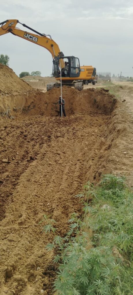
Clearing and Grubbing is the first activity before earthworks. It covers removal and disposal of vegetation including trees (up to 300 mm girth), bushes, shrubs, stumps, roots, grass, weeds, rubbish and top organic soil up to 150 mm thick. The scope includes draining stagnant water, backfilling pits created by uprooting trees and compacting to required density as per MoRTH Clause 305.3.4.

Clearing and Grubbing Methodology as per MoRTH Clause 201 Read More »

Earthwork
BC laying work

Bituminous Concrete

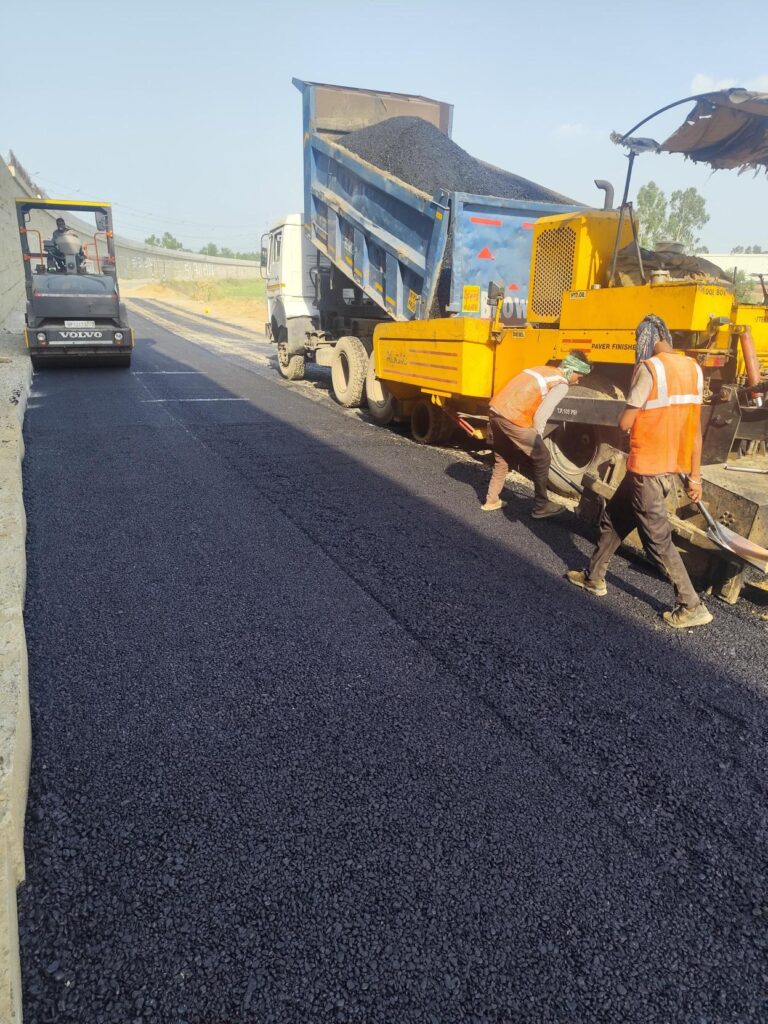
Top 9 Proven Steps for Bituminous Concrete (BC) | MoRTH Clause 507 Top 9 Proven Steps for Bituminous Concrete (BC) Construction Quick Summary: Bituminous Concrete (BC) is the final wearing course of flexible pavement laid in 30–50 mm thickness over DBM or bituminous base. Construction shall strictly follow MoRTH Clause 507, including approved mix design, controlled laying temperature, proper compaction and quality control tests. 1. Scope Methodology for laying of DBM in this project is detailed herein under. This method statement is based on parameters conforming to MoRTH, MS-2 Specifications. The construction of pavement layers on existing road involves the dismantling of existing bituminous layers, widening and strengthening of the existing road. This work covers preparation of surface, tack coat application, production of BC mix, transportation, laying, compaction, joint treatment and quality control testing in accordance with MoRTH Clause 507. 2. Reference Standards MoRTH Specifications – Clause 507 (5th Revision) IRC: SP: 84 – Manual of Specifications IS: 73 & IS: 15462 – Bitumen Standards IS: 2386 (All Parts) – Aggregate Testing Standards ASTM / AASHTO and MS-2 7th Rev– Marshall Mix Design Top Level Sheet – DBM (Dense Bituminous Macadam): Approved Mix Design & Approved GFC Drawings 3. Equipment Required Hot Mix Plant with automatic controls Self-propelled sensor paver with electronic, tamping/vibrating extendible screed (as per Clause 501.5) Tandem vibratory rollers Pneumatic Tyred Roller (PTR), 12–15 tonnes with minimum tyre pressure of 5.6 kg/cm² Bitumen pressure distributor/sprayer with accessories (as per Clause 502.4.1) Mechanical broom and air compressor for surface cleaning Core cutting machine for density testing Sufficient number of tippers for continuous and uninterrupted laying Materials & Job Mix Design Test Procedure of DBM & BC Mix Design (as per MoRTH & IRC Specifications) 1: Raise RFI for sampling of aggregates for DBM/BC mix design. 2: Sample the cold bin individual aggregates jointly. 3: Conduct individual gradation for aggregate as mentioned in MoRTH 500-10. 4: Blend the aggregate to meet the specified limits as mentioned in MoRTH 500-10. 5: Conduct the tests for aggregate to confirm its suitability for asphalt mix works: 6: AIV or LAAV, FI & EI, Stripping value, Water Absorption, Sand Equivalent value test to meet its suitability for DBM & BC as mentioned in MoRTH. 7: Feed the cold bin blending aggregate proportion in the Hot Mix Plant & take the individual hot bin aggregates. 8: Conduct specific gravity & water absorption test in the hot bin aggregates. Sl. No. 9: Conduct the individual gradation for aggregate & blend the aggregate to achieve the limit specified in MoRTH Table 500-10. 10: Feed the obtained blending proportion in the Hot Mix Plant and take the combined mix sample and check the combined gradation tests as mentioned in MoRTH 500-10. 11: Conduct the following tests for bitumen: Softening Point Test, Penetration Test, Viscosity Test from the approved bitumen source. 12: Prepare the mix with different binder content & find the Maximum Specific Gravity of the mix as per ASTM D-2041. 13: Cast the Marshall moulds with different binder content to check VMA, VFB, GSA, Air Voids, Stability & Flow of the mix. 14: With the obtained result plot the graph for Bulk Density, Marshall Stability, Air Voids, Flow, VMA & VFB. 15: All test data are interpreted & marked at which % all criteria passes. 16: Optimum Binder Content (OBC) has been found from chart. 17: Retained Stability Test conducted at OBC. 18: Refusal Density of the BC mix to be checked at 75, 150, 300 blows. 19: Marshall Quotient found for BC as per Table 7 of IRC SP:53-2002. 20: Confirmatory moulds casted & tested for Stability, Flow, VFB, VMA. Bituminous material of VG-40 grade shall confirm to the specifications of IS-73(2013). If modified binder is used then CRMB / PMB conforming to the requirement of CL.501.2.1, 507.2.1, IRC-SP-53-2010 and IS 15462-2004. Approved Aggregate and filler shall confirm two of MoRTH Cl.501.2 & Cl.507.2. Job Mix Formula (JMF): The Job Mix Formula (JMF) for Bituminous Concrete (BC) shall be developed and approved for use in the works in the presence of the Authority Engineer. The JMF shall include the following details: Source and location of all materials (bitumen, coarse aggregate, fine aggregate, and filler) Proportions of all constituent materials Binder type and percentage by weight of total mixture Coarse aggregate, fine aggregate, and mineral filler percentage Combined grading with specified sieve passing limits as per BC requirements Marshall test results as per Table 500-11 (Stability, Flow, Density, Air Voids, VMA, VFB) Aggregate compliance with MoRTH Clause 501.2 & Clause 507.2 Mixing, laying, and compaction temperature ranges Optimum Bitumen Content (OBC) and volumetric properties of mix Job Mix Design for BC shall be conducted in the Field Laboratory using Marshall Method. The materials shall be collected directly from the stockyard / storage tank and shall be checked for various physical requirements. The testing shall be carried out in the presence of the Consultant and submitted for approval. Approval of JMF: Approval shall be based on witnessed testing by the Independent Engineer. Samples shall be tested in in-house QC lab. Any change in material source requires submission of new JMF for approval prior to execution. Plant Trials: After laboratory approval, plant trials shall be conducted to ensure uniform mix production. Permissible variations shall comply with Table 500-13 limits. Laying Trials: Once the plant trials have been successfully completed and approved, the laying trials are executed to demonstrate that the proposed mix can be successfully laid and compacted in accordance with Clause 501. The laying trial shall be carried out on a suitable area which is not to form part of the works. The area of the laying trials shall be a minimum of 100 sq. m. of construction similar to that of the project road, and it shall be in all respects, particularly compaction, the same as the project construction, on which the bituminous material is to be laid. Information to AE is given of the proposed method for laying and compacting the material. The density

Bituminous Concrete Read More »

Bituminous Work
tackcoat spraying

Tack Coat in Road Construction | Methodology & IRC Guide

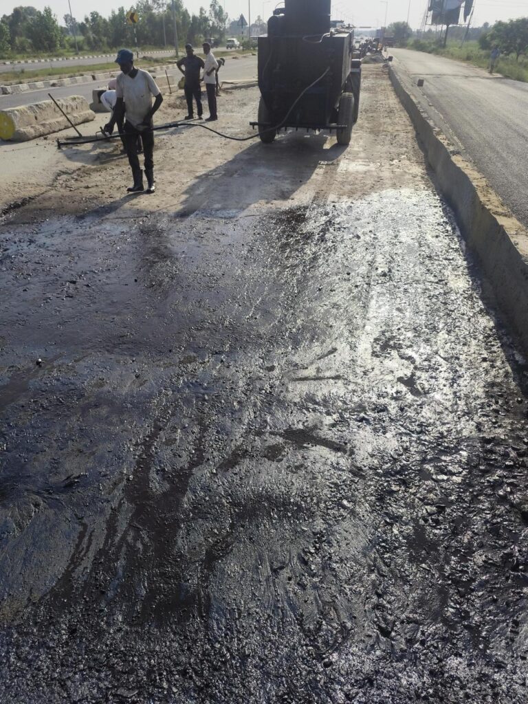
Tack Coat Methodology as per MoRTH Clause 503 | Highway Quality Test Tack Coat Methodology – Procedure, Application Rate, Equipment & Quality Control (MoRTH Clause 503) 📘 Primary Reference: MoRTH Specifications for Road and Bridge Works (India) 🌍 Global Relevance: This guide explains engineering principles and quality control practices that are widely applicable to highway and infrastructure projects worldwide. While based on MoRTH specifications, users should always follow the applicable project specifications, contract requirements, and local standards. What is Tack Coat? A Tack Coat is a thin, uniform application of rapid-setting cationic bitumen emulsion applied over a primed granular base or an existing bituminous surface before laying the next bituminous layer. It develops a strong bond between pavement layers, ensuring monolithic pavement behaviour, effective load transfer, and resistance to slippage, delamination, and premature pavement distress. Why Tack Coat Is Critical for Pavement Performance The performance and durability of flexible pavements largely depend on the quality of bonding between successive pavement layers. An improperly applied tack coat can result in layer slippage, delamination, shoving, surface cracking, and premature pavement failure under traffic loading. A properly applied tack coat provides adequate interlayer bond strength, improves shear resistance, and enables the pavement layers to act as a single structural unit, thereby enhancing pavement life and overall riding quality. Quick Technical Reference Parameter Details Applicable Specification MoRTH Specifications (5th Revision), Clause 503 Purpose To provide an effective bond between the existing surface and the new bituminous layer. Material Rapid Setting Cationic Bitumen Emulsion (RS-1 or RS-2) conforming to IS 8887. Application Rate 0.20–0.35 kg/m² (or as specified in the Contract Documents). Surface Condition Clean, dry, dust-free, and free from loose particles, oil, mud, and other deleterious materials. Application Equipment Mechanical Bitumen Pressure Sprayer with calibrated spray bar and hand spray lance for inaccessible locations. Traffic Allowance Traffic and subsequent paving shall be permitted only after the emulsion has completely broken and cured. Quality Check Ensure uniform coverage without streaks, missed areas, ponding, or excessive application. Applicable Codes & Specifications Standard / Specification Description MoRTH Specifications (5th Revision) Clause 503 – Tack Coat: Materials, equipment, application requirements, and quality control. IRC: SP:84 Manual of Specifications and Standards for Four-Laning of Highways through Public Private Partnership (PPP). IS 8887 Bitumen Emulsions for Roads – Specification covering cationic bitumen emulsions used for tack coat, prime coat, and surface dressing. Project Specifications / Approved Method Statement Project-specific requirements, approved Job Mix Formula (JMF), and Engineer’s instructions shall also be complied with during execution. Materials Requirements Material Requirement Bitumen Emulsion Rapid Setting Cationic Bitumen Emulsion (RS-1 or RS-2) conforming to IS 8887 and approved project specifications. Water Dilution shall not be permitted unless specifically approved by the Engineer and in accordance with the manufacturer’s recommendations. Storage Store the emulsion in clean tanks protected from contamination, excessive heat, and prolonged storage. Stir gently before use, if required. Material Approval Each batch shall be accompanied by the manufacturer’s test certificate and approved by the Engineer before application. Equipment Required Equipment Purpose Bitumen Pressure Distributor Calibrated mechanical pressure distributor with spray bar capable of applying the tack coat uniformly at the specified application rate. Mechanical Broom / Air Compressor Used to remove dust, loose particles, and other deleterious materials from the surface before tack coat application. Spray Tray / Calibration Tray Used to verify the spray rate and uniformity of the bitumen pressure distributor. Thermometer Used to monitor the temperature of the bitumen emulsion, where required. Hand Spray Lance Used for applying tack coat in areas inaccessible to the spray bar, such as edges, kerbs, median openings, and around structures. Measuring Tape & Marking Chalk Used to mark the application area and calculate the actual emulsion application rate. Personal Protective Equipment (PPE) Safety helmet, reflective jacket, gloves, safety shoes, and goggles for safe execution of the work. Tack Coat Application Methodology – Step-by-Step Procedure The tack coat shall be applied only after confirming that the underlying surface is clean, dry, structurally sound, and free from dust, loose particles, mud, oil, or any other deleterious material. The surface shall comply with the requirements of MoRTH Clause 503 before commencement of spraying. A uniformly applied tack coat develops a strong interlayer bond between the existing pavement and the new bituminous layer, enabling both layers to act as a single structural unit. Proper application improves shear resistance, prevents layer slippage, delamination, and premature pavement distress, thereby enhancing the durability and service life of the flexible pavement. The following methodology shall be adopted during execution of the work. Inspect the Existing Surface Before commencement of the tack coat application, inspect the underlying layer (WMM, DBM, BC, or an existing bituminous surface) and ensure that it has been approved for the next course by the Engineer. Verify that the surface complies with the approved line, level, camber/cross fall, and surface regularity requirements. Ensure that the pavement is structurally sound and free from potholes, segregation, bleeding, loose material, dust, mud, oil, standing water, or any other deleterious material that may adversely affect the bond between pavement layers. Clean the Surface Thoroughly Remove dust, dirt, loose aggregates, mud, laitance, and all foreign materials using mechanical broom, power blower, or compressed air. Oil, grease, and other contaminants shall be completely removed to ensure proper adhesion. Verify Weather Conditions Apply tack coat only during dry weather. The pavement surface shall be completely dry and free from standing water. Application shall not be carried out during rain, fog, or when adverse weather conditions may affect curing of the emulsion. Calibrate the Pressure Distributor Before commencement of work, calibrate the bitumen pressure distributor to ensure the specified spray rate, spray bar height, nozzle angle, and operating pressure. Check that all nozzles are clean and functioning properly to obtain a uniform spray pattern. Apply Tack Coat at the Specified Rate Spray the approved bituminous emulsion uniformly over the entire pavement surface at the rate specified in the approved Method Statement, MoRTH Specifications, or Project Quality Plan. Maintain a constant speed of the distributor


Tack Coat in Road Construction | Methodology & IRC Guide Read More »

Bituminous Work
prime coat spraying

Prime Coat

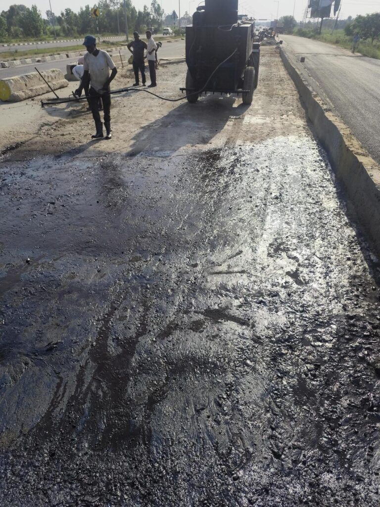
Prime Coat Procedure in Road Construction | Step-by-Step Site Execution (MoRTH Clause 502) The Prime Coat Procedure is one of the most important construction activities in flexible pavement construction. It involves the uniform application of a low-viscosity bituminous binder, generally SS-1 Grade Cationic Bitumen Emulsion, over an approved granular base such as Wet Mix Macadam (WMM), Water Bound Macadam (WBM), or other prepared non-bituminous layers before laying the first bituminous course. A properly executed Prime Coat penetrates the surface voids of the granular base, binds loose particles, minimizes dust, reduces excessive absorption of binder from the overlying asphalt layer, and develops a strong bond between the granular layer and the first bituminous course. The following step-by-step procedure is based on MoRTH Clause 502 and reflects the actual construction practices followed on NHAI, EPC, HAM, BOT, L&T ECC, APCO, Afcons, KNR, Dilip Buildcon, and other highway infrastructure projects. Step-by-Step Prime Coat Procedure Step 1 – Approval of the Granular Base Before Prime Coat Application The first and most important activity before applying the Prime Coat is to ensure that the underlying granular base course has been fully completed, tested, and approved by the Engineer. Prime coat shall only be applied over a prepared and accepted non-bituminous granular surface, such as Wet Mix Macadam (WMM), Water Bound Macadam (WBM), Crusher Run Macadam (CRM), or other approved granular base layers, in accordance with MoRTH Clause 502. Prime coat is intended to penetrate the surface voids of the granular base, bind loose particles, minimize dust, reduce absorption of binder from the overlying bituminous layer, and improve the bond between the base and the first asphalt course. However, it is important to understand that Prime Coat is not a corrective treatment. It cannot compensate for poor compaction, incorrect levels, inadequate thickness, segregation, or other construction defects. Therefore, all deficiencies in the granular base shall be rectified before prime coat is applied. Why Granular Base Approval is Necessary Applying prime coat over an unapproved or defective granular layer can permanently lock construction defects beneath the pavement. Since the base layer becomes inaccessible after bituminous paving, any deficiencies may lead to premature pavement failures such as rutting, settlement, uneven riding quality, cracking, stripping, or delamination. Formal approval by the Engineer confirms that the layer complies with the approved drawings, project specifications, and quality requirements before the next construction activity begins. Pre-Approval Checks by the Site Engineer Before requesting inspection from the Consultant or Engineer, the Site Engineer shall thoroughly verify that all quality control requirements have been satisfied. The following checks shall be completed: Inspection Item Requirement Layer Thickness Verified at approved chainages and complies with the approved drawings and MoRTH specifications. Compaction Field Density Test (FDT) results satisfy the specified density requirements. Surface Levels Finished levels comply with the approved longitudinal profile and design elevations. Cross Fall / Camber Measured cross fall matches the approved road geometry to ensure proper drainage. Surface Regularity Surface is smooth, uniform, and free from depressions, bumps, corrugations, or wheel marks. Segregation No coarse aggregate pockets, honeycombing, or segregated areas are visible. Damaged Areas Soft spots, potholes, ruts, loose material, and edge failures have been repaired. Drainage Surface is free from standing water and side drains are functional. Laboratory Test Records to be Verified The QA/QC Engineer shall ensure that all relevant laboratory and field test results are available, reviewed, and accepted before the application of Prime Coat. Gradation Test confirms compliance of the granular material with project specifications. Atterberg Limits (where applicable) comply with specified limits. Modified Proctor Test establishes the Maximum Dry Density (MDD) and Optimum Moisture Content (OMC). Field Density Test (FDT) confirms the required degree of compaction has been achieved. Moisture Content is within the permissible range during compaction. Thickness Measurements comply with approved drawings. Level Survey Records verify finished levels and cross fall. Consultant Inspection Before Approval Once internal quality checks have been completed, the work shall be offered for inspection. During inspection, the Consultant or Engineer typically verifies the overall condition of the surface, field density results, levels, cross fall, repaired locations, drainage condition, and general workmanship before granting approval for Prime Coat application. Common Mistakes by Fresh Engineers Applying Prime Coat before receiving formal approval from the Consultant. Ignoring segregated or honeycombed areas in the WMM surface. Proceeding with Prime Coat despite failed Field Density Test results. Assuming Prime Coat will conceal minor defects in the base layer. Neglecting to verify surface levels and cross fall before offering the work for inspection. Failing to repair edge failures, potholes, or loose aggregate before spraying. Site Engineer’s Checklist ✔ Granular base completed as per approved drawings. ✔ All quality control tests completed and accepted. ✔ Field Density Test results comply with MoRTH requirements. ✔ Surface levels and cross fall verified. ✔ Thickness measurements accepted. ✔ Surface free from segregation and damaged areas. ✔ No standing water or loose material present. ✔ Consultant approval obtained before Prime Coat application. Engineering Tip On most NHAI EPC projects, experienced engineers follow a simple principle: “Never use Prime Coat to hide defects in the granular base.” If the WMM or other base course is not accepted today, it will almost certainly cause problems after paving. Always repair the defects first, obtain formal approval, and only then proceed with Prime Coat application. Step 2: Surface Cleaning of Granular Base After obtaining approval of the prepared granular base, the entire surface shall be thoroughly cleaned before the application of the Prime Coat. Surface cleaning is one of the most critical activities because the prime coat must penetrate directly into the voids of the granular layer. The presence of dust, loose aggregate particles, mud, slurry, organic matter, standing water, or any other foreign material prevents proper penetration of the bituminous binder and significantly reduces the bond between the granular base and the first bituminous layer. In accordance with MoRTH Clause 501.8 and Clause 502, the prepared surface shall be maintained in a clean and satisfactory condition until the prime coat is applied.

Prime Coat Read More »

Bituminous Work

© 2026 HIGHWAY QUALITY TEST. All rights reserved.

WhatsAppNeed Help?
Scroll to Top