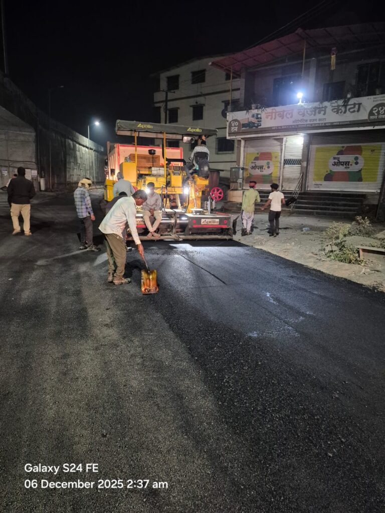
DBM Construction Methodology – MORTH Specifications, Plant & QA Guide
Author: Kishor Kumar | Category: Bituminous Works | As per MoRTH Clause 507
Dense Bituminous Macadam (DBM) is a dense-graded hot mix bituminous layer used as a binder or base course in flexible pavements. Proper DBM construction is critical to ensure load distribution, durability, and bonding between pavement layers.
Why DBM Quality Is Critical
The Dense Bituminous Macadam (DBM) layer forms the primary structural course in flexible pavement construction. It provides load distribution, structural strength, and surface uniformity before the Bituminous Concrete (BC) wearing course is laid.
This field-ready guide covers MoRTH specifications, asphalt plant requirements, mix design parameters, layer thickness criteria, temperature control, compaction standards, and complete QA/QC procedures—making it practical for site engineers, QA/QC professionals, and highway contractors.
Most premature pavement failures—such as rutting, fatigue cracking, shoving, and delamination—originate from poor DBM execution. Incorrect binder content, inadequate compaction, segregation during laying, improper joint construction, or temperature loss during transportation and paving can significantly reduce pavement service life.Since DBM acts as the structural backbone of flexible pavements, strict compliance with MoRTH specifications, proper mix design control, and systematic field quality checks are essential to ensure long-term pavement performance.
Quick Technical Reference
Applicable Codes & Specifications
Materials & Job Mix Design
Test Procedure of DBM & BC Mix Design (as per MoRTH & IRC Specifications)
- Source and location of all materials (bitumen, aggregates, filler)
- Proportions of all constituent materials
- Binder type and percentage by weight of total mix
- Coarse aggregate, fine aggregate, and mineral filler percentages
- Combined grading curve with specific sieve passing limits as per specification
- Marshall test results including stability, flow, density, and air voids as per Table 500-10 / 500-11 (as applicable)
- Compliance of aggregates with MoRTH Clause 507 requirements
- Mixing, laying, and compaction temperature ranges
- Optimum Bitumen Content (OBC) and volumetric properties (VMA, VFB, Air Voids)
Job Mix Design for DBM shall be conducted in the Field Laboratory using Marshall Method. The materials shall be collected directly from the stockyard / storage tank and shall be checked for various physical requirements.
The testing shall be carried out in the presence of the Consultant and submitted for approval.
Approval of JMF: Approval shall be based on witnessed testing by the Independent Engineer. Samples shall be tested in in-house QC lab. Any change in material source requires submission of new JMF for approval prior to execution.
MoRTH Clause 505.3.3 – Job Mix Formula (JMF)
Detailed Practical Example for DBM (Dense Bituminous Macadam)
1. Material Sources
| Material | Source | Location |
|---|---|---|
| 26.5 mm Aggregate | ABC Stone Crusher | Roorkee |
| 13.2 mm Aggregate | ABC Stone Crusher | Roorkee |
| Stone Dust | ABC Stone Crusher | Roorkee |
| Mineral Filler | UltraTech Cement | Roorkee |
| Bitumen | VG-40 | IOCL Refinery |
2. Aggregate Blend Proportions
| Material | Percentage of Total Aggregate |
|---|---|
| 26.5 mm Aggregate | 35% |
| 13.2 mm Aggregate | 30% |
| Stone Dust | 30% |
| Mineral Filler | 5% |
3. Combined Gradation
| Sieve Size | % Passing |
|---|---|
| 26.5 mm | 100 |
| 19 mm | 95 |
| 13.2 mm | 79 |
| 9.5 mm | 68 |
| 4.75 mm | 52 |
| 2.36 mm | 38 |
| 1.18 mm | 28 |
| 0.60 mm | 20 |
| 0.30 mm | 14 |
| 0.15 mm | 9 |
| 0.075 mm | 5 |
4. Marshall Mix Design Results
| Property | 4.0% | 4.5% | 5.0% |
|---|---|---|---|
| Marshall Stability (kN) | 12.8 | 15.4 | 14.0 |
| Flow (mm) | 2.6 | 3.1 | 4.0 |
| Air Voids (%) | 6.0 | 4.2 | 2.5 |
| VMA (%) | 14.2 | 15.1 | 16.0 |
| VFB (%) | 58 | 72 | 84 |
5. Optimum Binder Content
Selected Optimum Binder Content (OBC)
4.5% VG-40 Bitumen
6. Volumetric Properties
| Property | Value |
|---|---|
| Maximum Specific Gravity (Gmm) | 2.520 |
| Bulk Density (Gmb) | 2.398 |
| Air Voids (Va) | 4.84% |
| VMA | 15.1% |
| VFB | 67.9% |
7. Moisture Susceptibility Test (AASHTO T 283)
| Parameter | Value |
|---|---|
| Dry Strength | 1050 kPa |
| Wet Strength | 910 kPa |
| TSR | 86.7% |
| Status | PASS |
8. Temperature Requirements
| Activity | Temperature |
|---|---|
| Aggregate Heating | 170–180°C |
| Bitumen Heating | 150–165°C |
| Mixing Temperature | 155–165°C |
| Laying Temperature | 140–155°C |
| Compaction Temperature | 130–150°C |
Final Approved JMF Summary
| Parameter | Approved Value |
|---|---|
| Mix Type | DBM Grading-2 |
| Binder Grade | VG-40 |
| Optimum Binder Content | 4.5% |
| Marshall Stability | 15.4 kN |
| Flow | 3.1 mm |
| Air Voids | 4.84% |
| VMA | 15.1% |
| VFB | 67.9% |
| TSR | 86.7% |
| Mixing Temperature | 155–165°C |
| Compaction Temperature | 130–150°C |
Next Step After JMF Approval
Once the Job Mix Formula (JMF) is approved by the Engineer, the Contractor shall conduct a Plant Trial in accordance with MoRTH Clause 505.3.4 to verify that the hot mix plant can consistently produce a mix conforming to the approved JMF.
After successful completion and approval of the Plant Trial, a Laying Trial shall be carried out as per MoRTH Clause 505.3.5 to demonstrate that the approved mix can be laid and compacted satisfactorily under field conditions.
Only after successful approval of both the Plant Trial and Laying Trial shall full-scale production and paving operations commence on the project.
Detailed Example – Plant Trial Verification as per MoRTH Clause 505.3.4
Approved Job Mix Formula (JMF)
Assume the approved JMF for DBM is as follows:
| Sieve Size | JMF (% Passing) |
|---|---|
| 26.5 mm | 100 |
| 19.0 mm | 95 |
| 13.2 mm | 78 |
| 9.5 mm | 68 |
| 4.75 mm | 48 |
| 2.36 mm | 36 |
| 1.18 mm | 27 |
| 0.60 mm | 20 |
| 0.30 mm | 14 |
| 0.15 mm | 9 |
| 0.075 mm | 5 |
| Binder Content | 4.5% |
| Mixing Temperature | 160°C |
Step 1: Calculate Permissible Limits
| Parameter | JMF Value | Tolerance | Permissible Range |
|---|---|---|---|
| 19 mm | 95% | ±8% | 87% – 100% |
| 13.2 mm | 78% | ±7% | 71% – 85% |
| 9.5 mm | 68% | ±7% | 61% – 75% |
| 4.75 mm | 48% | ±6% | 42% – 54% |
| 2.36 mm | 36% | ±5% | 31% – 41% |
| 1.18 mm | 27% | ±5% | 22% – 32% |
| 0.60 mm | 20% | ±5% | 15% – 25% |
| 0.30 mm | 14% | ±4% | 10% – 18% |
| 0.15 mm | 9% | ±4% | 5% – 13% |
| 0.075 mm | 5% | ±2% | 3% – 7% |
| Binder Content | 4.5% | ±0.3% | 4.2% – 4.8% |
| Mixing Temperature | 160°C | ±10°C | 150°C – 170°C |
Step 2: Actual Plant Trial Results
| Parameter | Actual Result |
|---|---|
| 19 mm | 91% |
| 13.2 mm | 80% |
| 9.5 mm | 70% |
| 4.75 mm | 52% |
| 2.36 mm | 34% |
| 1.18 mm | 28% |
| 0.60 mm | 19% |
| 0.30 mm | 13% |
| 0.15 mm | 8% |
| 0.075 mm | 4.5% |
| Binder Content | 4.6% |
| Mixing Temperature | 158°C |
Step 3: Compliance Check
| Parameter | Permissible Range | Actual Result | Status |
|---|---|---|---|
| 19 mm | 87–100% | 91% | ✅ Pass |
| 13.2 mm | 71–85% | 80% | ✅ Pass |
| 9.5 mm | 61–75% | 70% | ✅ Pass |
| 4.75 mm | 42–54% | 52% | ✅ Pass |
| 2.36 mm | 31–41% | 34% | ✅ Pass |
| 1.18 mm | 22–32% | 28% | ✅ Pass |
| 0.60 mm | 15–25% | 19% | ✅ Pass |
| 0.30 mm | 10–18% | 13% | ✅ Pass |
| 0.15 mm | 5–13% | 8% | ✅ Pass |
| 0.075 mm | 3–7% | 4.5% | ✅ Pass |
| Binder Content | 4.2–4.8% | 4.6% | ✅ Pass |
| Temperature | 150–170°C | 158°C | ✅ Pass |
Example of Failure
Suppose the extracted binder content is 5.0%.
Permissible Range = 4.2% to 4.8%
Actual Result = 5.0%
Difference from JMF = +0.5%
Result: ❌ Non-Conforming
The Contractor must:
- Check calibration of bitumen pump.
- Verify bitumen flow meter.
- Inspect plant controls.
- Produce a fresh trial mix.
Practical Site Note
During Plant Trial, engineers generally perform:
- Hot Bin Analysis
- Extraction Test (Binder Content)
- Gradation After Extraction
- Temperature Monitoring
- Marshall Specimen Preparation
- Stability and Flow Verification
- Comparison with Approved JMF
Only after successful Plant Trial compliance can the Contractor proceed to Laying Trial under Clause 505.3.5.
Detailed Example – Plant Trial Verification as per MoRTH Clause 505.3.4
Approved Job Mix Formula (JMF)
Assume the approved JMF for DBM is as follows:
| Sieve Size | JMF (% Passing) |
|---|---|
| 26.5 mm | 100 |
| 19.0 mm | 95 |
| 13.2 mm | 78 |
| 9.5 mm | 68 |
| 4.75 mm | 48 |
| 2.36 mm | 36 |
| 1.18 mm | 27 |
| 0.60 mm | 20 |
| 0.30 mm | 14 |
| 0.15 mm | 9 |
| 0.075 mm | 5 |
| Binder Content | 4.5% |
| Mixing Temperature | 160°C |
Step 1: Calculate Permissible Limits
19 mm Sieve (Tolerance ±8%)
- JMF = 95%
- Upper Limit = 95 + 8 = 103% → Maximum possible = 100%
- Lower Limit = 95 − 8 = 87%
- Permissible Range = 87% to 100%
13.2 mm Sieve (Tolerance ±7%)
- JMF = 78%
- Upper Limit = 85%
- Lower Limit = 71%
- Permissible Range = 71% to 85%
9.5 mm Sieve (Tolerance ±7%)
- JMF = 68%
- Upper Limit = 75%
- Lower Limit = 61%
- Permissible Range = 61% to 75%
4.75 mm Sieve (Tolerance ±6%)
- JMF = 48%
- Upper Limit = 54%
- Lower Limit = 42%
- Permissible Range = 42% to 54%
2.36 mm Sieve (Tolerance ±5%)
- JMF = 36%
- Upper Limit = 41%
- Lower Limit = 31%
- Permissible Range = 31% to 41%
1.18 mm Sieve (Tolerance ±5%)
- JMF = 27%
- Upper Limit = 32%
- Lower Limit = 22%
- Permissible Range = 22% to 32%
0.60 mm Sieve (Tolerance ±5%)
- JMF = 20%
- Upper Limit = 25%
- Lower Limit = 15%
- Permissible Range = 15% to 25%
0.30 mm Sieve (Tolerance ±4%)
- JMF = 14%
- Upper Limit = 18%
- Lower Limit = 10%
- Permissible Range = 10% to 18%
0.15 mm Sieve (Tolerance ±4%)
- JMF = 9%
- Upper Limit = 13%
- Lower Limit = 5%
- Permissible Range = 5% to 13%
0.075 mm Sieve (Tolerance ±2%)
- JMF = 5%
- Upper Limit = 7%
- Lower Limit = 3%
- Permissible Range = 3% to 7%
Binder Content (Tolerance ±0.3%)
- JMF = 4.5%
- Upper Limit = 4.8%
- Lower Limit = 4.2%
- Permissible Range = 4.2% to 4.8%
Mixing Temperature (Tolerance ±10°C)
- JMF Temperature = 160°C
- Upper Limit = 170°C
- Lower Limit = 150°C
- Permissible Range = 150°C to 170°C
Step 2: Actual Plant Trial Results
| Parameter | Actual Result |
|---|---|
| 19 mm | 91% |
| 13.2 mm | 80% |
| 9.5 mm | 70% |
| 4.75 mm | 52% |
| 2.36 mm | 34% |
| 1.18 mm | 28% |
| 0.60 mm | 19% |
| 0.30 mm | 13% |
| 0.15 mm | 8% |
| 0.075 mm | 4.5% |
| Binder Content | 4.6% |
| Mixing Temperature | 158°C |
Step 3: Compliance Check
| Parameter | Permissible Range | Actual Result | Status |
|---|---|---|---|
| 19 mm | 87–100% | 91% | ✅ Pass |
| 13.2 mm | 71–85% | 80% | ✅ Pass |
| 9.5 mm | 61–75% | 70% | ✅ Pass |
| 4.75 mm | 42–54% | 52% | ✅ Pass |
| 2.36 mm | 31–41% | 34% | ✅ Pass |
| 1.18 mm | 22–32% | 28% | ✅ Pass |
| 0.60 mm | 15–25% | 19% | ✅ Pass |
| 0.30 mm | 10–18% | 13% | ✅ Pass |
| 0.15 mm | 5–13% | 8% | ✅ Pass |
| 0.075 mm | 3–7% | 4.5% | ✅ Pass |
| Binder Content | 4.2–4.8% | 4.6% | ✅ Pass |
| Temperature | 150–170°C | 158°C | ✅ Pass |
Example of Failure
Suppose the extracted binder content is 5.0%.
Permissible Range = 4.2% to 4.8%
Actual Result = 5.0%
Difference from JMF:
5.0 − 4.5 = +0.5%
Since the allowable variation is only ±0.3%, the result is:
❌ Non-Conforming
The Contractor must:
- Check calibration of bitumen pump.
- Verify bitumen flow meter.
- Inspect plant controls.
- Produce a fresh trial mix.
Practical Site Note
During Plant Trial, engineers generally perform:
- Hot Bin Analysis
- Extraction Test (Binder Content)
- Gradation After Extraction
- Temperature Monitoring
- Marshall Specimen Preparation
- Stability and Flow Verification
- Comparison with Approved JMF
Only after successful Plant Trial compliance can the Contractor proceed to Laying Trial under Clause 505.3.5.
MoRTH Clause 505.3.5 – Laying Trials (Dense Graded Bituminous Macadam)
Purpose of Laying Trial
After successful completion and approval of the Plant Trial under Clause 505.3.4, the Contractor shall conduct a Laying Trial to demonstrate that:
- The approved Job Mix Formula (JMF) can be laid satisfactorily in the field.
- The proposed paver can achieve the required thickness, line, level, and profile.
- The selected rolling pattern can achieve the specified density.
- The proposed construction methodology is suitable for large-scale production work.
The laying trial serves as a field validation of the approved mix and plant production process before commencement of actual paving works.
Requirements of Laying Trial
Laying Trials
Once the plant trials have been successfully completed and approved, the laying trials are executed to demonstrate that the proposed mix can be successfully laid and compacted in accordance with Clause 501.
The laying trial shall be carried out on a suitable area which is not to form part of the works. The area of the laying trials shall be a minimum of 100 sq.m of construction similar to that of the project road, and it shall be in all respects, particularly compaction, the same as the project construction on which the bituminous material is to be laid.
Information regarding the proposed method for laying and compacting the material shall be provided to the Engineer. The laying trial shall establish whether the proposed laying plant, compaction equipment, and methodology are capable of producing satisfactory results under actual field conditions.
The density of the finished paving layer shall be determined by taking cores no sooner than 24 hours after laying, or by any other method approved by the Engineer.
For Dense Graded Bituminous Macadam (DBM), the compacted layer shall achieve a minimum field density equal to or greater than 92% of the Theoretical Maximum Specific Gravity (Gmm) determined in accordance with ASTM D 2041.
Once the laying trials have been approved, the same plant, equipment, rolling pattern, and methodology shall be applied to the laying of the material on the project. No variation shall be permitted unless approved in writing by the Engineer.
The Engineer may, at his discretion, require additional laying trials if significant changes are proposed in the paving equipment, compaction equipment, construction methodology, or Job Mix Formula (JMF).
Tack Coat
Tack Coat shall consist of the application of a single coat of low viscosity liquid bituminous material on the existing bituminous surface using a calibrated boom pressure sprayer, ensuring uniform and continuous coverage.
The application shall be carried out at a controlled speed to achieve the specified rate of spray and ensure proper bonding between the existing surface and the subsequent bituminous layer. The tack coat shall be applied uniformly over the entire surface without streaking, pooling, or missed areas.
The treated surface shall be allowed to break and cure appropriately before placing the overlying bituminous layer to ensure effective adhesion and long-term pavement performance.
The trial section shall satisfy the following requirements:
Trial Area
- Be located on a suitable area approved by the Engineer.
- Not form part of the permanent works.
- Have a minimum area of 100 m².
- Be constructed using the same materials, equipment, layer thickness, and methodology proposed for the project road.
Example
For a DBM layer of 100 mm thickness:
- Trial Length = 25 m
- Trial Width = 4 m
- Area = 100 m²
This satisfies the minimum MoRTH requirement.
Contractor's Responsibilities Before Trial
Before starting the laying trial, the Contractor shall submit the following details to the Engineer:
Paver Details
- Make and model of paver.
- Screed type.
- Operating width.
- Sensor arrangement.
Roller Details
- Tandem Roller.
- Pneumatic Tyred Roller (PTR).
- Vibratory Roller.
Rolling Pattern Example
| Roller Type | Number of Passes |
|---|---|
| Vibratory Roller | 4 Passes |
| Pneumatic Tyred Roller (PTR) | 6 Passes |
| Finish Roller | 2 Passes |
Construction Methodology
- Hauling arrangement.
- Temperature control measures.
- Paving sequence.
- Rolling sequence.
- Joint construction method.
Objectives of Laying Trial
1. Uniform Laying
The mix shall be laid without:
- Segregation.
- Dragging.
- Surface tearing.
- Excessive temperature loss.
2. Thickness Control
The paver shall achieve the specified compacted thickness.
Example:
Required DBM Thickness = 100 mm
| Core Location | Measured Thickness |
|---|---|
| Core 1 | 101 mm |
| Core 2 | 98 mm |
| Core 3 | 100 mm |
Result: Thickness acceptable.
3. Surface Regularity
- Smooth riding quality.
- Correct camber.
- Correct cross fall.
- Proper longitudinal profile.
4. Compaction Capability
The rolling pattern shall achieve the required field density. This is the most important objective of the laying trial.
Density Requirement for DBM
MoRTH specifies that the compacted DBM layer shall have a minimum field density equal to or greater than 92% of the Theoretical Maximum Specific Gravity (Gmm).
Gmm Determination
Gmm is determined as per ASTM D 2041.
Example:
Gmm = 2.520
Required Density = 92% × 2.520 = 2.318 g/cc
Minimum Acceptable Field Density = 2.318 g/cc
Density Verification by Core Test
Cores shall be extracted at least 24 hours after paving.
Core Density Results
| Core No. | Bulk Density (g/cc) |
|---|---|
| 1 | 2.340 |
| 2 | 2.332 |
| 3 | 2.325 |
Average Density:
(2.340 + 2.332 + 2.325) ÷ 3 = 2.332 g/cc
Percent Density Calculation
Density (%) = (Field Density ÷ Gmm) × 100
= (2.332 ÷ 2.520) × 100
= 92.54%
Result: ✅ PASS
Because 92.54% > 92%
Example of Failure
Assume:
- Field Density = 2.280 g/cc
- Gmm = 2.520
Density (%) = (2.280 ÷ 2.520) × 100
= 90.48%
Result: ❌ FAIL
Because 90.48% < 92%
Possible Reasons for Failure
- Insufficient roller passes.
- Delayed rolling.
- Low mix temperature.
- Inadequate roller weight.
- Excessive layer thickness.
- Improper rolling pattern.
Corrective Measures
- Modify rolling sequence.
- Increase roller passes.
- Increase compaction effort.
- Adjust paving temperature.
- Improve hauling arrangements.
- Conduct a fresh laying trial.
Approval of Laying Trial
| Parameter | Requirement |
|---|---|
| Thickness | As per drawing |
| Density | ≥ 92% of Gmm |
| Surface Finish | Satisfactory |
| Regularity | Acceptable |
| Segregation | Nil |
| Construction Method | Acceptable |
Only after satisfactory compliance shall the laying trial be approved.
Requirement After Approval
- Same JMF shall be used.
- Same hot mix plant shall be used.
- Same paver shall be used.
- Same roller combination shall be used.
- Same rolling pattern shall be used.
- Same construction methodology shall be used.
Any change requires written approval from the Engineer.
When a New Laying Trial May Be Required
- JMF changes.
- Aggregate source changes.
- Bitumen source changes.
- Paver changes.
- Roller combination changes.
- Layer thickness changes.
- Significant construction problems occur.
Practical Site Checklist During Laying Trial
- ✔ Mix Temperature at Plant
- ✔ Mix Temperature at Site
- ✔ Paver Speed
- ✔ Loose Layer Thickness
- ✔ Roller Sequence
- ✔ Number of Passes
- ✔ Surface Appearance
- ✔ Segregation Check
- ✔ Joint Quality
- ✔ Core Density Testing
- ✔ Thickness Verification
- ✔ Surface Regularity Check
Workflow After JMF Approval
JMF Approval
      ↓
Plant Trial (Clause 505.3.4)
      ↓
Plant Trial Approval
      ↓
Laying Trial (Clause 505.3.5)
      ↓
Density & Thickness Verification
      ↓
Engineer Approval
      ↓
Full Scale DBM Production
Interview Question
Q. What is the minimum field density requirement for DBM during Laying Trial as per MoRTH Clause 505.3.5?
Answer: The compacted DBM layer shall achieve a field density equal to or greater than 92% of the Theoretical Maximum Specific Gravity (Gmm) determined as per ASTM D 2041, verified through core cutting or another approved method.
Transportation, Paving & Compaction Methodology (Enhanced)
1. Transportation of Bituminous Mix
Hot Mix shall be transported in rear tipping dumpers of minimum 10T capacity or higher, ensuring uninterrupted supply to the paver. All vehicles shall be clean, leak-proof, and properly insulated where required.
To prevent heat loss, each dumper shall be fully covered with heavy-duty tarpaulin immediately after loading. The mix temperature shall be monitored at plant, dispatch, and site to ensure compliance with MoRTH specifications.
2. Paving Operations
Paving shall be carried out using a high-performance Asphalt Paver equipped with hydraulically extendable screed capable of maintaining precise longitudinal and transverse profiles, gradients, and levels.
Pavers of approved make shall be deployed, capable of paving up to 11.0 m width for full carriageway laying. For service roads and restricted areas, pavers capable of paving up to 5.5 m width shall be used.
Continuous and uniform paving shall be ensured without segregation, with automatic sensor control wherever applicable to maintain specified thickness and smooth riding quality.
3. Temperature Control
The temperature of the mix at the time of laying shall be strictly maintained as per approved Job Mix Formula (JMF). Any material outside permissible temperature limits shall be rejected at site.
Table 500-2: Mixing, Laying and Rolling Temperatures for Bituminous Mixes (°C)
| Bitumen Grade | Bitumen Temp (°C) | Aggregate Temp (°C) | Mixing Temp (°C) | Laying Temp (°C) | Rolling Temp (Start ≥ °C) |
|---|---|---|---|---|---|
| VG-40 | 160 - 170 | 160 - 175 | 160 - 170 | 150 - 165 | 150 Min |
| VG-30 | 150 - 165 | 160 - 175 | 150 - 165 | 145 - 165 | 140 Min |
| VG-20 | 145 - 165 | 150 - 165 | 145 - 165 | 140 - 160 | 135 Min |
| VG-10 | 140 - 160 | 150 - 165 | 140 - 160 | 130 - 150 | 130 Min |
Note: Rolling must be completed before the mat cools down to the specified minimum rolling temperatures to ensure proper compaction and interlocking of aggregates.
4. Rolling & Compaction Sequence
Breakdown rolling shall commence immediately behind the paver and shall start only when the mix temperature is below 120°C and stable enough to avoid displacement or cracking.
Rolling shall be completed before the mix temperature falls below 80°C to ensure optimum density and interlocking of aggregates.
Compaction shall be achieved using a combination of:
- 10T Double Drum Vibratory Roller (Primary Compaction)
- Pneumatic Tyre Roller (Secondary Compaction / Kneading Effect)
Final rolling shall ensure elimination of roller marks and achievement of uniform density across the entire surface width.
5. Quality Control & Testing
Finished surface levels shall be jointly verified with the Consultant and compared with approved design levels and tolerances.
Field density shall be checked using Sand Replacement Method or Nuclear Density Gauge at specified frequency as per QA/QC plan.
Core samples shall be extracted using a calibrated core cutting machine. All laboratory tests including thickness, density, and bitumen content shall be carried out to ensure compliance with approved specifications and JMF.
6. Opening to Traffic
The newly laid bituminous surface shall be opened to traffic only after complete cooling to ambient temperature or after a minimum curing period of 24 hours, whichever is later, and subject to approval of the Engineer.
7. Safety & Environmental Management
- Caution boards shall be installed at entry, exit, and all hazardous locations of work zone.
- Continuous barricading with reflective tape shall be provided along active work areas.
- Trained flagmen / signalmen shall be deployed at high traffic density locations.
- Reflective signage and blinking lights shall be provided during night operations.
- Hot mix plant shall be operated with valid pollution control measures in place.
- Noise control and emission control devices shall be maintained in working condition.
- Construction waste shall be disposed of in designated approved locations only.
- All necessary precautions shall be taken to avoid public inconvenience and environmental impact.
8. Contractor’s Technical Remarks
- Manpower and machinery deployment is indicative and may be adjusted based on site requirements and progress.
- Any modification in execution methodology shall be implemented only after prior approval from the Consultant/Engineer.
- Full compliance with MoRTH, IRC, and project-specific specifications shall be ensured at all stages of execution.
Additional Items
- Spreading in restricted areas shall be done manually.
- Hot joints shall be executed before earlier material cools to 100°C. No laying in standing water.
- During rain, laying shall stop when water accumulates; rollers may continue compaction.
- All tippers shall be covered with tarpaulin during rain.
Daily Progress Reports
- Date of operation with RFIs
- Material quantity records
- Laydown records (location, layer, time, temperature)
- Plant and labour deployment
- Laboratory and field test records
DAILY PROGRESS REPORTS SHALL RECORD:
- Date of Operation with RFIs
- WMM/DBM used within PCC operations to weighed prior to dispatch.
- Lay down Record Sheets indicating location, layer, lane, time, load, temperature.
- Plant/Labor used.
- Appropriate Laboratory/Field Test records.
COMPOSITION OF DENSE GRADED BITUMINOUS MACADAM
| Grading | 1 | 2 |
|---|---|---|
| Nominal aggregate size | 37.5 mm | 26.5 mm |
| Layer Thickness | 75-100 mm | 50-75 mm |
| 45.00 | 100 | - |
| 37.50 | 95-100 | 100 |
| 26.50 | 63-93 | 90-100 |
| 19.00 | - | 71-95 |
| 13.20 | 55-75 | 56-80 |
| 9.5 | - | - |
| 4.75 | 38-54 | 38-54 |
| 2.36 | 28-42 | 28-42 |
| 1.18 | - | - |
| 0.600 | - | - |
| 0.300 | 7-21 | 7-21 |
| 0.150 | - | - |
| 0.075 | 2-8 | 2-8 |
| Bitumen Content | Min 4.0% | Min 4.5% |
QUALITY CONTROL INSPECTION & FREQUENCY OF TESTING:
| Layer | Inspection Stage | Test / Parameter | Standard | Frequency | Acceptance Criteria | |||||||||||||||||||||||||||||
|---|---|---|---|---|---|---|---|---|---|---|---|---|---|---|---|---|---|---|---|---|---|---|---|---|---|---|---|---|---|---|---|---|---|---|
| Dense Bituminous Macadam (DBM) | Inspection at Source – Properties of Binder & Aggregate | Quality of Binder | IS:1201 to IS:1220 & IS:15462 | 1 Sample / Lot |
Ordinary Bitumen complying with IS:73 (2013) Modified Bitumen complying with IRC:SP:53 (2010) | |||||||||||||||||||||||||||||
| Aggregate Impact Value | IS:2386 (Part 4) | 1 Test / 350 m³ | 27% (Max) | |||||||||||||||||||||||||||||||
| Los Angeles Abrasion Value | IS:2386 (Part 4) | As & when Required | 35% (Max) | |||||||||||||||||||||||||||||||
| Combined Flakiness & Elongation Index | IS:2386 (Part 1) | 1 Test / 350 m³ | 35% (Max) | |||||||||||||||||||||||||||||||
| Stripping Value | IS:6241 | 1 Test / Source | Minimum retained coating 95% | |||||||||||||||||||||||||||||||
| Soundness Test | IS:2386 (Part 5) | 1 Test / Source |
12% max with Sodium Sulphate 18% max with Magnesium Sulphate | |||||||||||||||||||||||||||||||
| Water Absorption Value | IS:2386 (Part 3) | 1 Test / Source | 2% (Max) | |||||||||||||||||||||||||||||||
| Sand Equivalent Value | IS:2720 (Part 37) | 1 Test / Source | 50% (Min) | |||||||||||||||||||||||||||||||
| % Age of Fractured Face | IS:2386 (Part 1) | As & when Required | 90% of material retained on 4.75 mm sieve shall have at least 2 fractured faces | |||||||||||||||||||||||||||||||
| Plasticity Index | IS:2720 (Part 5) | 1 Test / Source | 4% (Max) | |||||||||||||||||||||||||||||||
| Inspection at Source – Properties of Mix | Aggregate Grading (Mix Aggregates) | IS:2386 (Part 1) |
1 Test / 400 MT of Mix Minimum 2 Tests / Plant / Day |
MoRTH Spec (5th Rev.) Table 500-10 | ||||||||||||||||||||||||||||||
| Marshall Stability | ASTM D-1559 / AASHTO T245 |
Set of 3 Specimens / 400 MT of Mix Minimum 2 Sets / Plant / Day | As per Table 500-10 of MoRTH Specification | |||||||||||||||||||||||||||||||
| Marshall Flow | ASTM D-1559 / AASHTO T245 |
Set of 3 Specimens / 400 MT of Mix Minimum 2 Sets / Plant / Day | As per Table 500-10 of MoRTH Specification | |||||||||||||||||||||||||||||||
| Air Voids | ASTM D-2726 |
Set of 3 Specimens / 400 MT of Mix Minimum 2 Sets / Plant / Day | As per Table 500-10 of MoRTH Specification | |||||||||||||||||||||||||||||||
| Voids in Mineral Aggregate (VMA) | ASTM D-2726 |
Set of 3 Specimens / 400 MT of Mix Minimum 2 Sets / Plant / Day | As per Table 500-10 of MoRTH Specification | |||||||||||||||||||||||||||||||
| Voids Filled by Bitumen (VFB) | ASTM D-1559 |
Set of 3 Specimens / 400 MT of Mix Minimum 2 Sets / Plant / Day | As per Table 500-10 of MoRTH Specification | |||||||||||||||||||||||||||||||
| Binder Content | ASTM D-2172 |
1 Test / 400 MT of Mix Minimum 2 Tests / Plant / Day |
4% (Min) for Grade-I 4.5% (Min) for Grade-II | |||||||||||||||||||||||||||||||
| Maximum Specific Gravity of Mix (Gmm) | ASTM D-2041 |
1 Test / 400 MT of Mix Minimum 2 Tests / Plant / Day | As per Approved Mix Design | |||||||||||||||||||||||||||||||
|
Water Sensitivity Test (if retained coating in stripping test is less than 95%) | AASHTO T283 | 1 Test / Mix (When Source of Material Changes) | 80% (Min) | |||||||||||||||||||||||||||||||
| Control of Temperature | Control of Temperature of Binder in Boiler & Aggregate in Dryer | MoRTH Specifications | Every Day Prior to Production Starts |
Aggregate Temp: 150°C–170°C Binder Temp: 150°C–165°C Discharge Temp: 150°C–165°C Modified Bitumen: Aggregate Temp: 150°C–185°C Binder Temp: 165°C–185°C Discharge Temp: 150°C–170°C | ||||||||||||||||||||||||||||||
| Permissible Variations of Plant Mix from Job Mix Formula | Aggregate Grading | MoRTH Specifications | NA |
|
| Category | Item | Reference / Standard | Frequency | Requirement / Criteria |
|---|---|---|---|---|
| In-process Inspection | Check level control of paver | MORTH Specifications | At regular close intervals | - |
| Temperature of mix before laying and rolling | MORTH Specifications | At regular close intervals |
Laying Temp. 140°C (Min) Rolling Temp. 90°C (Min) | |
| Acceptance Criteria | Control of Compaction (Field Density) | ASTM-D 2726 | 1 Test / 700 m² | As per MORTH Cl 903.4.2 |
| Tolerance in Surface Level | Standard survey practice | As per Specification | +6 mm or -6 mm | |
| Surface Regularity | IRC-SP-16 | As & when Required | Bituminous Base Course 6 mm | |
| Binder Tolerance | ± 0.3% | |||
| Mixing Temperature Tolerance | ± 10°C | |||
INSPECTION PLAN:
- Approval of WMM TOP layer – Inspection & Testing required
- Spreading / fill layers – Inspection required
- Final Layer – Inspection & Testing required
- Density checks – Inspection & Testing required
SAFETY MEASURES:
- All safety measures shall be as per approved EHS Plan.
Common Field Problems & Remedies
- Segregation: Improve handling, reduce drop height
- Low Density: Increase rolling passes or temperature
- Fatty Surface: Reduce binder content, improve gradation
- Cold Joints: Proper joint heating and rolling
Safety & Best Practices
- Mandatory PPE for all personnel
- Proper traffic diversion and barricading
- Safe handling of hot bituminous materials
- Maintain complete QC documentation
Frequently Asked Questions (FAQ)
DBM must achieve at least 98% of Marshall Density as per MoRTH.
No. DBM shall not be laid during rain or on wet surfaces.
DBM acts as a binder/base course, while BC is the wearing course with finer gradation.
🏗️ Highway Construction Methodology Hub
Standard construction methodologies for highway works as per MoRTH 5th Revision and IRC Specifications.
- ✅ Prime Coat Application Methodology ➡️
- ✅ Tack Coat Application Methodology ➡️
- ✅ Dense Bituminous Macadam (DBM) Methodology ➡️
- ✅ Bituminous Concrete (BC) Methodology ➡️
- ✅ Profile Corrective Course of DBM ➡️
- ✅ Use of Waste Plastic in Bitumen ➡️
- ✅ Use of Waste Plastic in Road Construction ➡️
- ✅ Thermoplastic Road Marking Methodology ➡️
