Uncategorized

Vicate Apparatus.jpg

Final Setting Time of Cement

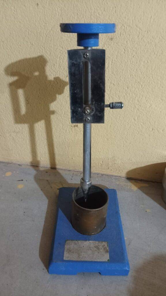
Final Setting Time of Cement Test – IS 4031 (Part 5) Objective: The final setting time of cement represents the total time elapsed from the moment water is added to cement until the paste completely loses its plasticity and develops sufficient rigidity to resist a standard penetration, as specified in IS 4031 (Part 5). This property is critical for assessing the suitability of cement in highway, pavement, and concrete construction projects. Incorrect setting times can adversely affect concrete strength, workability, pavement performance, and long-term durability. Therefore, the final setting time test is a mandatory quality control procedure in laboratory and field conditions. 1. Reference Standards IS 4031 (Part 5): Methods of Physical Tests for Hydraulic Cement – Determination of Setting Times IS 4031 (Part 4): Determination of Standard Consistency of Cement Paste IS 8112: Specification for 43 Grade Ordinary Portland Cement (OPC) IS 12269: Specification for 53 Grade Ordinary Portland Cement (OPC) 2. Apparatus Required Vicat apparatus with needle having annular attachment and a 10 mm needle for initial setting time comparison. Non-absorbent base plate or glass plate for placing the mould. Balance with an accuracy of ±0.01 g for weighing cement. Measuring cylinder with an accuracy of ±1 ml for water measurement. Mixing bowl or non-reactive container for paste preparation. Trowel or spatula for mixing and leveling the paste. Stopwatch or digital timer for precise time measurement. Controlled ambient conditions (temperature 27 ± 2°C and relative humidity ≥ 50%) as per IS recommendations. Audit Tip: Ensure the Vicat needle and annular attachment are clean, undamaged, and calibrated before testing. Calibration errors are a frequent cause of non-compliance during NHAI and third-party audits. 3. Sample Preparation Cement Sample: Take 300 g of cement passing completely through a 90 µm IS sieve. Sieving ensures uniform particle size and removes any lumps, which is essential for accurate determination of the final setting time as per IS 4031 (Part 5). Handle the cement carefully to avoid contamination by moisture or dust, which can significantly alter the test results. Water Content: Determine the water required for the standard consistency (P) of the cement paste according to IS 4031 (Part 4). Accurate measurement of water is critical; deviations may lead to inconsistent setting times and unreliable results. Mixing Procedure Gradually add the measured water to the sieved cement to form a paste. Slow addition ensures complete wetting of cement particles and prevents dry pockets. Mix thoroughly for 2–3 minutes using a spatula or trowel. The paste should be smooth, uniform, and free of lumps, with no segregation of water or dry particles. Immediately proceed to fill the Vicat mould placed on a non-absorbent base plate. Level the surface carefully using a trowel to remove trapped air and ensure uniform contact with the needle. Maintain ambient conditions within recommended ranges (temperature 27 ± 2°C, relative humidity ≥ 50%) to prevent accelerated or delayed setting. Audit Note: Incorrect mixing techniques or improper water content can lead to premature or delayed setting. Always follow IS procedures strictly to ensure accurate and repeatable results. 4. Test Procedure – Determination of Final Setting Time Step 1: Filling the Vicat Mould Place the Vicat mould on a non-absorbent base plate. Fill the mould completely with freshly mixed cement paste. Level the surface gently using a trowel or spatula to remove any air bubbles and ensure uniform paste thickness. Step 2: Using the Vicat Apparatus Attach the needle with annular attachment to the Vicat apparatus. Immediately start the stopwatch at the moment water is added to cement. Lower the needle gently onto the cement paste at regular intervals, typically every 5–10 minutes. Observe the impressions on the paste surface. Cement is considered finally set when the needle touches the surface, but the annular attachment fails to make any indentation. Final Setting Criterion: The cement paste is considered finally set when it has completely lost plasticity and can resist the penetration of the Vicat annular attachment. This is the basis for determining the final setting time as per IS 4031 (Part 5). 5. Recording & Calculation Record the elapsed time from the instant water is added to the cement until the paste meets the final setting criterion. Final Setting Time (minutes) = Time at final set – Time of water addition It is recommended to perform the test at least three times and report the average value to account for variability and ensure accuracy. 6. Comparison: Initial vs Final Setting Time Parameter Initial Setting Time Final Setting Time Vicat Needle 10 mm needle Needle with annular attachment Indicates Start of setting Completion of setting Standard Limit ≥ 30 minutes ≤ 600 minutes Site Control Placing & handling Finishing & curing 7. Common Site & Laboratory Mistakes Incorrect water quantity or deviation from standard consistency. Starting the stopwatch after mould filling instead of at water addition. Not cleaning or calibrating the Vicat needle and annular attachment between observations. Testing under high temperature or low humidity, affecting setting times. Using bent, worn, or damaged Vicat needles. Delays in transferring paste into the mould, causing premature setting. Quality Insight: Failure to follow IS procedures for mixing, water content, and testing can lead to non-compliance, material rejection, or project delays. Repeated errors may result in supplier de-empanelment during audits. 8. Practical Tips for Highway and Pavement Projects Always use fresh cement samples, sieved through a 90 µm IS sieve immediately before testing. Maintain laboratory temperature around 27 ± 2°C and relative humidity ≥ 50%. Perform both initial and final setting time tests to fully understand cement behavior. Document all observations and deviations for audit purposes. Use clean, calibrated equipment to avoid measurement errors. 9. Conclusion The final setting time of cement is a critical quality parameter for highway, pavement, and concrete construction. Adhering strictly to IS 4031 (Part 5) ensures reliable measurement, proper workability, adequate strength development, and long-term durability of infrastructure projects. Regular training, audit compliance, and careful attention to mixing, water content, and ambient conditions are essential for accurate determination of the final setting

Final Setting Time of Cement Read More »

Ductility Test

Ductility Test of Bitumen – Procedure, Apparatus & Limits (IS Method) Home › Bitumen Tests › Ductility Test of Bitumen Ductility Test of Bituminous Material – IS Standard Procedure 1. OBJECTIVE To determine the ductility of bituminous material, which measures the distance a bitumen sample can stretch before breaking. 2. APPARATUS Ductility testing machine Briquette moulds Hot knife 3. PROCEDURE Melt the bitumen sample to 75–100°C above its softening point until it becomes fully fluid. Strain the material through a 90-micron sieve, pour into the mould assembly, and place on a brass plate after applying a mixture of glycerine and dextrin to all mould surfaces. Allow it to stand for 30–40 minutes, then place the mould assembly in a water bath maintained at 27°C for 30 minutes. Remove mould from water bath and level the surface using a hot knife to cut off excess material. After trimming, place the specimen back in the water bath at 27°C for 85–95 minutes. Remove sides of mould and attach the clips to the ductility machine carefully without applying initial strain. Start the machine, setting pointer to zero, and apply tension at a uniform speed of 50 ± 2.5 mm/min. Ensure the sample remains immersed in water at a depth of at least 10 mm throughout the test. Record the distance (in cm) at which the bitumen thread breaks. This is the ductility value. 4. RESULTS The ductility value is the distance stretched (in centimeters) by the moving end of the briquette specimen at the point where the bitumen thread breaks. 5. LIMITS (ACCORDING TO IS REQUIREMENTS) A35 & S35 Grade Bitumen: Minimum ductility = 50 cm at 27°C All Other Grades: Minimum ductility = 75 cm at 27°C

Ductility Test Read More »

Compressive Strength of Cube

Concrete Cube Casting & Compressive Strength Testing (IS:516) 1. Objective To prepare, cast, cure, and test concrete cube specimens of size 150 × 150 × 150 mm or 100 × 100 × 100 mm to determine compressive strength of concrete at specified ages (usually 7 days and 28 days). 2. Apparatus Required Cube moulds – 150 mm or 100 mm Mixing tray and scoop Tamping rod (16 mm diameter) Trowel Concrete mixer (if required) Curing tank (27 ± 2°C) Compression Testing Machine (CTM) 3. Preparation of Cube Moulds Clean moulds to remove dust and hardened mortar. Assemble moulds properly and tighten bolts. Apply thin uniform oil layer on internal faces. Check alignment and squareness of mould. 4. Sampling and Mixing of Concrete Sample concrete from freshly mixed batch. Mix thoroughly until uniform colour and consistency are achieved. Start casting immediately to avoid loss of workability. 5. Casting of Concrete Cubes Fill mould in three equal layers. Distribute concrete evenly around mould. 6. Compaction of Concrete Compact each layer by rodding or vibration. Manual compaction: 35 strokes per layer. Rods to penetrate into the previous layer. Tap mould sides gently to remove air voids. Finish top surface smoothly using trowel. 7. Identification and Initial Storage Date of casting Grade of concrete Cube number / location Store cubes undisturbed for 24 hours at 27 ± 2°C. 8. Curing of Concrete Cubes Demould cubes after 24 ± ½ hours. Immediately immerse in clean water. Maintain curing temperature at 27 ± 2°C. Continue curing till testing age. 9. Compression Testing of Cubes (IS:516) Remove cube from curing tank (SSD condition). Clean cube and CTM platens. Measure dimensions (nearest 0.2 mm). Place cube centrally on CTM platen. Apply load gradually at ≈140 kg/cm²/min. Record maximum load at failure. Note: Improper centring causes eccentric loading and wrong test results. 10. Calculation of Compressive Strength Compressive Strength (N/mm²) = Maximum Load at Failure ÷ Loaded Area 11. Cube Size – Area – Thumb Rules Cube Size Loaded Area 150 mm Cube 225 cm² 100 mm Cube 100 cm² Fast Site Calculation Rules 150 mm cube → Load (kg) ÷ 225 | Load (kN) ÷ 22.5 100 mm cube → Load (kg) ÷ 100 | Load (kN) × 10 12. Sampling Frequency (IS Practice – Simplified) Concrete Quantity No. of Samples Total Cubes 1 – 5 m³ 1 3 6 – 15 m³ 2 6 16 – 30 m³ 3 9 31 – 50 m³ 4 12 Each additional 50 m³ +1 +3 13. Reporting of Results Calculate strength of each cube. Round off to nearest whole number. Average of 3 cubes = representative strength. Variation limits must be satisfied. Concrete Strength Acceptance Criteria (±15% Rule Explained) Basic Rule For any set of 3 cubes (one sample): Calculate average strength Each cube must lie within: 0.85 × Average (−15%) 1.15 × Average (+15%) If even one cube is outside this range, the sample is REJECTED, irrespective of average strength. Key Strength Values – M25 Concrete Characteristic strength (fck) = 25 N/mm² Standard deviation (assumed) = 4 N/mm² Target mean strength = fck + 1.65 × S = 25 + (1.65 × 4) = 31.6 N/mm² CASE–1: Single Sample (Small Quantity Concrete) Concrete Quantity = 5 m³ As per IS practice → 1 sample (3 cubes) Acceptance Criterion (Special Case) When only one sample is available: Average strength ≥ fck + 4 = 29 N/mm² Cube Strengths (N/mm²) Average 0.85 × Avg 1.15 × Avg 19, 26, 16 20.3 17.3 23.3 Reasons for Rejection ❌ Average strength less than 29 N/mm² ❌ Cubes 26 and 16 N/mm² outside ±15% range Final Decision: ❌ CONCRETE REJECTED CASE–2: Multiple Samples (Normal Quantity Concrete) Concrete Quantity = 28 m³ Samples required = 3 samples (9 cubes) Acceptance Criteria Each cube ≥ fck − 2 = 23 N/mm² Overall average ≥ fck + 4 = 29 N/mm² ±15% variation satisfied for each sample Sample-wise Results Sample Cube Strengths (N/mm²) Average 0.85 × Avg 1.15 × Avg 1 33, 29, 32 31.3 26.6 36.0 2 24, 32, 28 28.0 23.8 32.2 3 25, 29, 32 28.7 24.4 33.0 Overall Average Strength (31.3 + 28.0 + 28.7) ÷ 3 = 29.3 N/mm² Acceptance Check (As per IS Acceptance Criteria) ✅ ±15% Variation Check: All individual cube strengths fall within the permissible range of 0.85 × Average to 1.15 × Average for their respective samples. This confirms uniformity in batching, mixing, compaction, and curing of concrete. ✅ Minimum Individual Strength Check: Each tested cube has achieved a compressive strength greater than or equal to fck − 2, i.e. 23 N/mm² for M25 concrete. No cube strength is below the minimum permissible limit. ✅ Average Strength Check: The overall average compressive strength of all samples is 29 N/mm² or higher, which satisfies the requirement of fck + 4 for acceptance of concrete under normal sampling conditions. ✅ Quality and Compliance Confirmation: Since variation, individual strength, and average strength criteria are all satisfied, the concrete meets the strength acceptance requirements prescribed under IS practice for M25 grade. Final Decision: ✅ CONCRETE ACCEPTED One-Line Site Memory Rules Single sample → Average ≥ fck + 4 Multiple samples → Each cube ≥ fck − 2 ±15% variation is compulsory Final Takeaway Concrete cube testing is the backbone of quality control. Correct casting, curing, testing, and acceptance checks ensure strength, durability, and compliance with IS standards. ✅ Why Concrete is ACCEPTED Uniform Strength: All cube test results lie within ±15% of their respective sample averages, indicating proper batching, mixing, compaction, and curing. Sufficient Individual Strength: No cube strength is below fck − 2 (23 N/mm² for M25), ensuring minimum safety at the individual specimen level. Adequate Average Strength: The overall average compressive strength is ≥ fck + 4 (29 N/mm²), satisfying IS acceptance requirements. Statistical Reliability: Multiple samples provide confidence that at least 95% of concrete will achieve the characteristic strength. ❌ Why Concrete is REJECTED (When Failure Occurs) One or more cube values fall outside ±15% of the sample

Compressive Strength of Cube Read More »

soil.jpg

Soil Test

Highway Material Testing Index – As per MoRTH 5th Revision A complete reference of all laboratory and field tests for each layer of highway construction — from Subgrade to Rigid Pavement — based on MoRTH 5th Revision, IS, and IRC standards. Earthwork & Subgrade Moisture Content – IS:2720 (Part 2) Sieve Analysis – IS:2720 (Part 4) Atterberg Limits – IS:2720 (Part 5) Compaction / Proctor Test – IS:2720 (Part 7 & 8) California Bearing Ratio (CBR) – IS:2720 (Part 16) Field Density – Core Cutter / Sand Replacement (IS:2720 Part 28) DCP / Plate Load Test Borrow Area / Embankment Material Tests Granular Sub-Base (GSB) Gradation – IS:2386 (Part 1) Flakiness & Elongation Index – IS:2386 (Part 1) Los Angeles Abrasion Value – IS:2386 (Part 4) Water Absorption – IS:2386 (Part 3) Field Density & Moisture – IS:2720 (Part 28) Degree of Compaction – (Min. 97% of MDD) Wet Mix Macadam (WMM) Aggregate Impact Value – IS:2386 (Part 4) Gradation Check – IS:2386 (Part 1) Proportioning of Materials – MoRTH Clause 406 Field Density (Core Cutter / NDT) Moisture Content Check Layer Thickness Verification Bituminous Layers (BM / DBM / BC) Binder Content Determination Marshall Stability & Flow Value – ASTM D1559 / MoRTH 507 Bitumen Penetration, Softening Point, Ductility, Specific Gravity – IS:1203–1208 Aggregate Stripping Value – IS:6241 Bitumen Extraction Test Core Density / Thickness Test Temperature Control Record Rigid Pavement (Concrete Pavement) Cement Tests – IS:4031 Coarse Aggregate Tests – IS:2386 (Part 1–4) Fine Aggregate Tests – Sieve, Silt, Bulking, Specific Gravity Concrete Mix Design – IS:10262 / IRC:44 Workability (Slump Test) – IS:1199 Compressive Strength (Cube Test) – IS:516 Flexural Strength (Beam Test) – IS:516 (Part 5) Pavement Thickness (Core Cutting) Surface Regularity / Texture Depth Additional / Common Tests Water Quality Test – IS:456 / IS:10500 Reinforcement Bar Tests – IS:1786 Geotextile / Geogrid Tensile Strength Test Temperature / Weather Records Looking for detailed procedures? Explore our complete testing guides below Soil Testing Aggregate Testing Bitumen & Bituminous Testing Concrete Testing © 2025 Highway Quality Test | Developed to promote Quality Road Construction through Standardized Testing

Soil Test Read More »

Scroll to Top
WhatsApp