Flyash Embankment Construction: Step-by-Step Guide
Quick Summary
- Core Material: Flyash (min density 0.9 g/cc)
- Earth Cover: Topsoil or granular cover for stability
- Layer Thickness: 200–400 mm (depending on roller)
- Compaction: 8–10 ton vibratory roller, ≥95% MDD
- QC Tests: Atterberg Limits, Modified Proctor, Moisture Content, Field Density
- Safety: Traffic signage, dust suppression, protection of water bodies
This comprehensive guide explains flyash embankment construction in accordance with IRC: SP: 58-2001 and MoRT&H specifications. Learn materials selection, core design, earth cover, compaction methods, quality control, and safety measures for flyash embankment construction.
Materials Selection for Flyash Embankment Construction
All materials must be approved by the Engineer. The core material is flyash, encapsulated by earth cover to ensure stable flyash embankment construction and durability for highway projects.
Geotechnical Properties of Flyash
| Property | Typical Range | Notes |
|---|---|---|
| Appearance | Fine powder, grey to tan | N/A |
| Fineness | Mostly < 0.075 mm | Fine-grained material suitable for embankment cores |
| Specific Gravity | 1.90–2.55 | Lower than most soils |
| Dry Density (Loose) | 0.9–1.2 g/cc | Minimum required for compaction |
| Compacted Dry Density | 1.0–1.4 g/cc | Varies with compaction method |
| Permeability | 10⁻⁴–10⁻⁷ cm/sec | Low but higher than cohesive soils |
| Plasticity | Non-plastic | Ideal for embankment cores |
| pH | 8–10 (Alkaline) | Influences leachate |
Download All Flyash Embankment Reference Documents (PDF)
Step-by-Step Flyash Embankment Construction Process
Setting Out
After completion of site clearance, the limits of embankment shall be marked by fixing pegs on both sides at regular intervals. The chainage boards and working bench mark shall be set outside the limits of construction areas.
Material
The materials to be used in embankment construction should be characterised to determine their physical and engineering properties. The fly-ash conforming to specifications as per IRC SP: 58-2001 shall be used.
Clearing and Grubbing
This work consists of cutting, removing and disposal of trees, bushes, shrubs, roots, grass, rubbish, etc., from the alignment and within the area of road land which will accommodate road embankment, drains, and such other areas as specified on the drawings.
During clearing and grubbing, the contractor shall take adequate precautions against soil erosion, water pollution, etc. All trees, stumps, etc., falling within fill area should be cut to at least 500 mm below ground level and pits shall be filled with suitable material and compacted thoroughly so as to make the surface at these points conform to the surrounding area.
Stripping and Storing of Top Soil
When constructing embankment using fly ash, the top soil from all areas to be covered by the embankment foundation should be stripped to specified depth not exceeding 150 mm. Top soil should not be unnecessarily trafficked either before stripping or when in stockpiles. Also, these shall not be surcharged or otherwise loaded and multiple handling should be kept to minimum.
Setting Out
After the site has been cleared, the limits of embankment should be set out true to lines, curves, slopes, grades and sections as shown on the drawings. The limits of the embankment should be marked by fixing batter pegs on both sides at regular intervals as guides before commencing the construction.
The embankment should be built sufficiently wider than the design dimensions so that surplus material may be trimmed, ensuring that the remaining material is of the desired density and in position specified, and conforms to the specified slopes. Bench marks and other stakes should be maintained as long as in the opinion of the engineer, they are required for the work.
Compacting the Ground Supporting Embankment
Where necessary, the original ground should be levelled, scarified, mixed with water and then compacted by rolling so as to achieve minimum 97 percent of MDD determined as per IS:2720 (Part 8) for the foundation soil.
Handling and Transportation of Fly-Ash
Fly ash is typically delivered to the site in covered dumper truck to minimize loss of moisture and dusting. Fly ash generally contains moisture to prevent dusting.
Spreading and Compaction
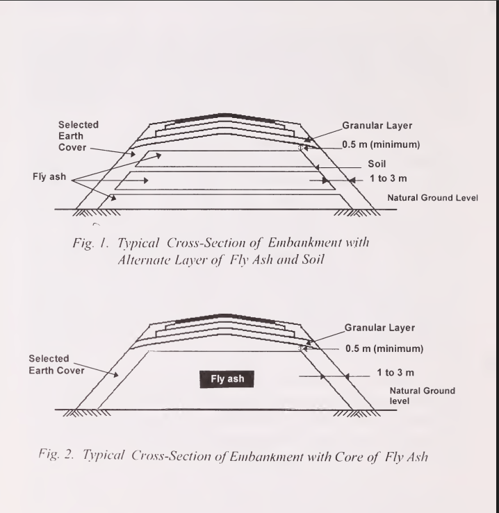
Intermediate soil layers are often provided in the fly ash embankment for ease of construction, to facilitate compaction of ash and to provide adequate confinement. Such layers minimise liquefaction potential also.
- Embankment with intermediate soil layers can be adopted in case height of the embankment is more than 3 m.
- The compacted thickness of intermediate soil layers shall not be less than 200 mm.
- One or more layers shall be constructed depending upon the design requirements.
- The vertical distance between such layers may vary from 1.5 to 3 m.
- The top 0.5 m of embankment should be constructed using selected earth to form the subgrade for the road pavement.
- Typical cross-sections of fly ash embankment with and without intermediate soil layers are shown in Fig. 1 below.
Fly Ash Embankment Typical Cross Section
Side Soil Cover and Compaction Control
The side soil cover of required width shall be provided along with the core and mechanically compacted as the embankment progresses upwards. The addition of side cover subsequent to the construction of the core is prohibited. The fill material should be spread by mechanical means, finished by motor grader.
Smaller vibratory rollers with dead weights of 10 to 15 kN perform well on loose layer thickness of the order of 100-150 mm. Medium weight vibratory rollers with dead weights in the range 60-100 kN provide satisfactory compaction for loose layer thickness of about 250 mm. When vibratory roller of dead weight 80-100 kN are used, loose layer thickness up to 400 mm can be adopted. When compaction is carried out using only static roller of 80-100 kN weight, loose layer thickness shall not exceed 200 mm.
The cover soil and fly-ash should be laid simultaneously before compaction, to ensure confinement of fly-ash. Clods or hard lumps in cover soil shall be broken to have a maximum size of 50 mm.
Moisture Content Control
Moisture content of the fill material shall be checked at the site prior to commencement of compaction. Moisture content of fly-ash laid for compaction shall normally vary from OMC ± 2% (determined as per IS: 2720 Part 8). The moisture content limits can be varied depending on weather conditions by the Engineer-in-charge, provided specified compaction is achieved and there is no dust problem. At higher moisture contents, fly ash may liquefy and become difficult to handle and compact.
Moisture content of cover soil shall be maintained at its OMC. Where water is required to be added, it shall be sprinkled from a water tanker fitted with a sprinkler capable of applying water uniformly without flooding. The water shall be mixed thoroughly by blading, discing or harrowing or by suitable means until uniform moisture content is obtained throughout the depth of the layer. If the material delivered to the construction site is too wet, it shall be dried by aeration and exposure to sun till acceptable moisture content is achieved.
Compaction Requirements
Fly ash can be compacted using vibratory or static rollers. Each layer of fly-ash shall be thoroughly compacted to the specified density. The construction of fly ash core and earth cover on the sides should proceed simultaneously. Each compacted layer shall be finished parallel to the final cross-section of the embankment.
- Minimum dry density after compaction shall be 97% of MDD as per IS: 2720 (Part 8).
- For embankment length equal to 1.5 times the height of embankment in bridge abutments, 100% compaction shall be required.
Drainage and Protection
Fly ash embankments should be benched at 4 to 6 m vertical intervals to drain surface water run-off to the ends of the embankment rather than allowing full volume of run-off to travel down the face of the embankment to the toe. Run-off from pavement surfaces should be collected and discharged into proper drainage system.
Finishing Operations
Finishing operations shall include shaping and dressing of shoulders, verge, roadbed and side slopes to conform to alignment, levels, cross-sections and dimensions shown in drawings or as directed by the Engineer subject to tolerance limits. Both upper and lower ends of side slopes shall be rounded off to improve appearance and to merge the embankment with adjacent terrain.
Quality Control
Quality of compacted material shall be controlled through periodic checks on the compaction process or the end product, singly or in combination as directed. The end product must conform to specifications. The number of tests to be conducted and acceptance criteria shall be as outlined in MoRTH Specifications for Road and Bridge Works, Section 900.
Quality Control and Safety
Compaction Standards
| Location | Required Density |
|---|---|
| General Embankment | ≥ 97% MDD |
| Bridge Abutments | ≥ 100% MDD |
QC Test Items
| QC Test | Code | Frequency |
|---|---|---|
| Atterberg Limits | IS: 2720 Pt 5 | 2 / 3000 m³ |
| Modified Proctor | IS: 2720 Pt 8 | 2 / 3000 m³ |
| Moisture Content | IS: 2720 Pt 2 | 1 / 250 m³ |
| Field Density | IS: 2720 Pt 28 | 1 / 1000 m² |
Safety and Environmental Measures
- Traffic safety: signage, flagmen
- Protection of water bodies
- Dust suppression
Frequently Asked Questions (FAQ)
What is a flyash embankment?
A flyash embankment is an earth structure where flyash is used as the core material, covered by earth layers for stability, strength, and durability in highway construction.
What is the minimum density required for flyash core?
The minimum dry density for the flyash core must be 0.9 g/cc to ensure proper compaction and stability.
How thick should embankment layers be?
Compacted layers of flyash embankment should not exceed 200–400 mm in loose thickness, depending on the roller type used.
Which standards govern flyash embankment construction?
Construction should follow IRC SP 58-2001 and MoRT&H specifications, with soil testing per IS 2720 series.
What quality control tests are required?
Tests include Atterberg Limits (IS 2720 Pt 5), Modified Proctor (IS 2720 Pt 8), Moisture Content (IS 2720 Pt 2), and Field Density (IS 2720 Pt 28) as per specified frequencies.
