Embankment Construction Methodology with Quality Control – MoRTH Clause 305
Scope of Work
The work shall consist of construction of embankment with approved and specified materials obtained from approved borrow areas or suitable material obtained from roadway excavation and drain excavation and in accordance with clause 305 of MORTH specifications.
Reference Standards
- MoRTH Specifications – Section 305 (5th Revision)
- IRC SP: 84
- IS 2720 Series – Soil Testing
- Approved Project Drawings
Manpower & Responsibilities
- Construction Manager
- Engineer / Supervisor
- Land Surveyor
- Material Engineer
- Safety Supervisor
- Helpers
Construction Manager
He shall be overall responsible for the activity including:
- Planning and organizing resources required for execution in consultation with the Project Manager.
- Implementation of safety requirements during the work including utility services protection.
- Ensuring all relevant tests are conducted as per specification.
- Maintaining all QA/QC records as per contract requirements.
- Coordinating with the consultant engineer for obtaining necessary approvals for completed activities.
Engineer / Supervisor
Responsibilities include:
- Deployment of required resources at site as per planning.
- Execution of work as per approved drawings.
- Maintaining quality control as per specifications.
- Implementation of safety regulations at site.
- Obtaining approvals for completed works from consultant/authority.
Land Surveyor
Responsibilities include:
- Establishing reference points for alignment and levels.
- Ensuring correct setting out of works.
- Checking and recording levels of completed work.
- Coordinating with consultant staff for final approval of finished works.
Material Engineer
Responsibilities include:
- Implementation of quality procedures as per approved plan.
- Ensuring all materials meet specification requirements.
- Conducting required laboratory and field tests as per standards.
- Maintaining complete material testing records and reports.
Safety Supervisor
Responsibilities include:
- Ensuring safe execution of all site activities.
- Implementation of project safety plan and guidelines.
- Monitoring compliance of safety measures at site.
Setting Out
After completion of site clearance, the limits of embankment shall be marked by fixing pegs on both sides at regular intervals. The chainage boards and working bench mark shall be set outside the limits of construction areas.
Material Selection & Borrow Area Testing
Selection of Material and Borrow Areas
Material
The material used in embankment shall be soil, moorum, gravel, reclaimed material from pavement, fly ash, pond ash, a mixture of these or any other material approved by the AE. It shall be free of logs, stumps, roots, rubbish and any other material likely to deteriorate or affect the stability of the embankment. The material for embankment shall be obtained from the approved source with preference to the material becoming available from nearby roadway excavation or any other excavation under the contract. The material requirements shall be in accordance with Clause 305.2 of MORTH specifications.
- These materials shall be free from logs, stumps, roots, rubbish or any other ingredients likely to affect the stability of the embankment. The material that has LL less than 55%, PI less than 25%, and Free Swell Index less than 50% shall be used for embankment construction. The material which is having lab MDD 15.2 minimum as per IS: 2720 Part-8 shall be used in embankment filling. The sample from the borrow area shall be brought to the laboratory and tested for the above requirements.
- Clods and hard humps of earth will be broken to a maximum size of 75 mm for embankment.
- If the moisture content (NMC) is less than OMC, the water shall be added by sprinkling considering evaporation losses, so that at the time of compaction it is in the range of 1% above to 2% below the optimum moisture content.
- If NMC is more than OMC, the material can be allowed to dry by exposure to the sun.
EMBANKMENT/STRUCTURE BACK FILLS
The following type of material shall be considered un-suitable.
- Material from swamps, marshes and bogs.
- Peat, log, stump and perishable material.
- Soil classified as OL, OI, OH or Pt. in accordance with IS: 1498.
- Material susceptible to spontaneous combustion.
- Material in frozen condition.
- Clay having LL exceeding 70 and PI exceeding 45 for Embankment.
- Clay having LL exceeding 50 and PI exceeding 25 for Subgrade.
- Material with salts resulting in leaching in the embankment.
- Soils having free swelling index more than 50% shall not be used as filled material.
- Soil having acceptedbelow free swelling index (non-expensive soils) shall be used up to 500 mm below sub-grade/embankment top.
- Fill material having soluble Sulfate content exceeding 1.9 gm. of Sulfate per liter (As per BS: 1377 test 10) not to be deposited with 500 mm in contact with concrete structure or cement bound materials forming part of permanent work.
- Fill material having total Sulfate content exceeding 0.5% by mass. (Tested as per BS: 1377 test 9) shall not be deposited with 500 mm of metallic item forming part of Permanent Work.
- The maximum size of coarse material in earth mixture shall not exceed 75 mm for embankment fill and 50 mm for sub grade fill.
- Soil material shall satisfy density requirement as given in BELOW
Density Requirements for Embankment & Subgrade Material
| Sl. No | Type of Work | Maximum Laboratory dry unit weight when tested as per IS: 2720 (Part 8) |
|---|---|---|
| 1 | Embankments up to 3.0 m high not subjected to extensive flooding. | Not less than 15.2 KN/cum or 1.55 gm /cc. |
| 2 | Embankment exceeding 3.0 m ht. or Embankment of any height subject to long period of inundation. | Not less than 16.0 KN/cum 1.631 gm/cc. or 1.6 gm/cc |
| 3 | Sub grade and earthen shoulder / backfill | Not less than 17.5 KN/cum or 1.784 gm/cc |
Note: Materials used shall satisfy design CBR i.e. soaked CBR shall not be less than 12% and 10% as per design locations for Heavy weight fill material. This below is not applicable for light weight fill material.
Compaction Requirement
The Embankment /sub grade material shall be compacted in one or more layer as per contract. The compacted field density shall meet minimum density requirement as given in BELOW
Compaction Requirements for Embankment & Sub grade
| Sl. No | Type of work/material | Relative Compaction % of max. Laboratories dry density as per IS: 2720 (Part 8) |
|---|---|---|
| 1 | Sub grade and earthen shoulder | Not less than 97% |
| 2 | Embankment | Not less than 95% |
| 3 | Ground Supporting the Embankment / Subgrade | Not less than 90% |
Borrow Material
The borrow material shall comply with Clause 305.2.2.2 of the MORTH specifications.
Testing Requirements
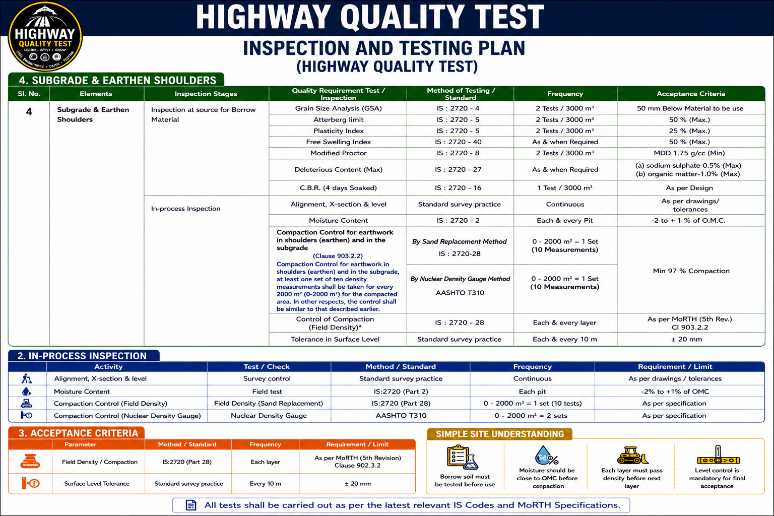
Field QA/QC Checklist – Embankment / Subgrade Construction
Prior to commencement and during execution of embankment/subgrade works, the site engineer shall ensure compliance with approved drawings, specifications, and ITP requirements. All checks shall be verified jointly by Site QA/QC and Execution team.
- Material source shall be strictly from approved borrow area with valid environmental and authority clearances.
- All incoming material shall conform to approved acceptance criteria as per contract specifications and ITP.
- Gradation of soil/borrow material shall remain within approved envelope limits; any deviation shall be immediately brought under control.
- Laboratory results for MDD and OMC (as per Modified Proctor Test) shall be available and duly approved before compaction.
- CBR value of borrow material shall meet the requirement of approved pavement design and design traffic loading.
- Calibrated moisture measuring device (speedy moisture meter / nuclear gauge) shall be available at site for real-time moisture control.
- All plant and equipment deployed shall be in sound working condition with valid calibration/inspection records where applicable.
- Proper survey setting-out shall be completed prior to work commencement, including establishment of TBM, bench marks, and control points for line and level verification.
Minimum Equipment Deployment – Embankment Works
Adequate plant and machinery shall be deployed to achieve specified layer thickness, compaction, and productivity targets without compromising quality.
- Hydraulic Excavator for excavation and material handling
- Dozer for spreading and rough grading of fill material
- Tipper Trucks for controlled haulage and placement
- Motor Grader for profile formation and layer finishing
- Vibratory Roller (smooth drum / pad foot as applicable) for compaction
- Water Tanker with spray arrangement for moisture conditioning
- Tractor Trolley / auxiliary transport as required for site logistics
- Survey instruments (Auto level / Total station) for layout and level control
Method Statement – Embankment Construction (Detailed Site Execution & QA/QC Control)
1. Pre-Construction Activities (Site Preparation & Engineering Controls)
- Before commencement of earthwork, the full embankment footprint shall be demarcated at site using total station survey. All control points, benchmarks (TBM), and reference pillars shall be established and jointly verified by Execution and QA/QC teams.
- Toe lines shall be marked beyond the design slope to ensure adequate compaction at edges and to prevent slope failure or inadequate density at outer zones.
- Existing ground condition shall be physically inspected to identify soft pockets, organic soil, waterlogged zones, or unsuitable strata. Such areas shall be recorded in site register for corrective action prior to fill placement.
-
A pre-start joint inspection shall be carried out between Client/Authority representative and Contractor QA/QC to confirm readiness of:
- Survey setting out
- Borrow area approval
- Lab test reports (MDD, OMC, CBR)
- Equipment deployment
2. Foundation Preparation (Ground Treatment)
- Natural ground shall be cleared of vegetation, debris, topsoil and any unsuitable material up to required depth as per drawings/specifications.
- Exposed formation shall be scarified to a depth of 150–200 mm, watered to OMC, and compacted using vibratory roller to achieve minimum 95% MDD.
- Field density testing shall be carried out in each compacted strip. No embankment fill shall commence until foundation layer is accepted by QA/QC.
- In case of very soft or unstable ground, removal and replacement with approved granular material shall be carried out in layers with proper compaction control.
3. Borrow Material Management & Quality Control
- Borrow areas shall be pre-approved and tested for suitability (gradation, Atterberg limits, CBR, MDD, OMC).
- Each borrow area shall have a material identification code and traceability record maintained at site laboratory.
- Random sampling shall be done during excavation to ensure consistency of material properties throughout execution.
- Material failing to meet specification shall be rejected at source itself and not allowed to enter site.
4. Material Transport, Spreading & Layer Control
- Material shall be transported by tippers with controlled unloading to avoid segregation and uneven dumping.
-
Each layer shall be placed in uniform thickness:
- Max 250 mm loose thickness for vibratory compaction
- Max 200 mm loose thickness for static compaction
- Dozer shall be used for initial spreading, followed by motor grader to achieve line, level, camber and cross slope as per drawings.
- Oversized particles (>75 mm) and hard clods shall be broken or removed before compaction.
5. Moisture Conditioning (Critical Control Parameter)
- Moisture content shall be strictly controlled within OMC ±2% range at time of compaction.
- Water sprinkling shall be done using calibrated water tankers ensuring uniform distribution without formation of puddles or soft zones.
- If soil is dry → water shall be added and mixed using grader/disc harrow for uniform distribution.
- If soil is wet → material shall be aerated, spread and allowed to dry until moisture reduces to acceptable range.
- Moisture verification shall be done randomly using Speedy Moisture Meter / oven drying method.
6. Compaction Methodology (Field Execution Control)
- Compaction equipment shall be selected based on soil type and approved trial stretch (vibratory roller / pneumatic roller / static roller).
-
A trial stretch (minimum 50–100 m) shall be conducted to establish:
- Number of passes required
- Optimum roller speed
- Layer thickness suitability
- Rolling shall start from lower edge towards higher edge in longitudinal direction parallel to road centerline.
- Each pass shall overlap previous pass by minimum one-third roller width to ensure uniform density.
- Compaction shall continue until field density ≥ 95% / 97% of MDD (as per specification requirement).
7. Quality Control, Testing & Acceptance
- Field density testing shall be carried out using Sand Replacement Method / Nuclear Density Gauge at specified frequency as per approved ITP.
- Each layer shall be jointly inspected by Site Engineer and QA/QC before approval for next layer.
-
Any area failing density requirement shall be:
- Reworked
- Moisture corrected
- Recompacted
- All test records shall be properly documented in site register and QA/QC reports for traceability.
8. Layer Progression & Final Formation
- No subsequent layer shall be allowed without written clearance of previous layer by QA/QC department.
- Embankment shall be built up systematically in layers ensuring slope stability, drainage control, and compaction uniformity.
- Final formation level shall be achieved strictly as per approved drawings with tolerance limits as per MORTH Table 900-1.
- Completed embankment shall be protected from erosion, rainfall damage, and traffic until next construction stage.
Compaction Requirements
| Location | Minimum Density |
|---|---|
| Embankment Body | ≥ 95% of Modified Proctor MDD |
| Top 500 mm (Subgrade) | ≥ 97% of Modified Proctor MDD |
Field Quality Control Procedures
Density Control
- Sand Replacement Method – IS 2720 (Part 28)
- Frequency:
- One set of ten measurements of density for each 3000 sqm of compacted area for embankment work and 2000 sqm for subgrade work, or closer as required to yield the minimum number of test results for evaluating a day's work on statistical basis.
Moisture Control
| Parameter | Requirement |
|---|---|
| Moisture Content |
Construction Tolerances (MoRTH 305)
| Item | Permissible Tolerance |
|---|---|
| Finished Level | ± 20 mm |
| Width | +100 mm / −50 mm |
| Side Slopes | ± 0.5% |
| Layer Thickness | ± 25 mm |
Inspection Checklist – Embankment Works (QA/QC Control Points)
1. Pre-Construction Stage (Readiness Verification)
- Borrow area approval obtained from Engineer and compliance with environmental clearance ensured.
- Laboratory results for MDD, OMC, gradation, and CBR established and approved before commencement.
- Existing ground condition verified, including removal of vegetation, topsoil, and unsuitable material.
- Formation level compacted and accepted by QA/QC prior to first layer placement.
2. During Construction Stage (Process Control)
- Layer thickness strictly controlled as per specification (200–250 mm loose thickness depending on compaction method).
- Moisture content maintained within OMC ±2% at time of compaction.
- Rolling pattern followed as per approved trial stretch (overlap, sequence, and speed controlled).
- Field density tests carried out as per approved frequency and recorded in QA/QC register.
- Any deviation in density or moisture immediately corrected before proceeding further.
3. Post-Construction Stage (Acceptance & Handover)
- Final formation levels and cross slopes verified against approved drawings using total station / auto level.
- Side slopes checked for stability, uniformity, and protection against erosion.
- Drainage arrangements ensured to prevent water stagnation or seepage.
- Final inspection and written approval obtained from Engineer before proceeding to next pavement layer.
Frequently Asked Questions – Embankment Construction (MoRTH 305 / Field Practice)
What is the required compaction for embankment works?
As per MoRTH specifications, embankment shall be compacted to a minimum of 95% of Maximum Dry Density (MDD), while subgrade (top layer) shall achieve 97% MDD.
What moisture range is acceptable during compaction?
Moisture content shall be maintained within Optimum Moisture Content (OMC) ± 2% to ensure effective compaction and stability.
Which field density test is adopted at site?
Field density is determined using Sand Replacement Method as per IS 2720 (Part 28), and in some cases Nuclear Density Gauge as per approved procedure.
What is the testing frequency for field density?
Minimum one test shall be conducted per 3000 m² of compacted layer for embankment layer and 2000m2 for subgrade layer or as per approved ITP/ project quality plan.
Why is embankment quality control critical?
Proper quality control ensures long-term stability of embankment, prevents differential settlement, avoids pavement cracking, and enhances overall service life of the highway structure.
