HIGHWAY QUALITY TEST

Precision Testing. Proven Quality. Safer Infrastructure.

Method Statement for Earthwork | Embankment and Subgrade Construction (MoRTH)

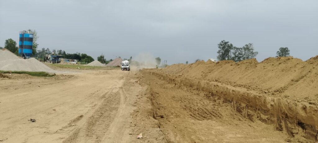
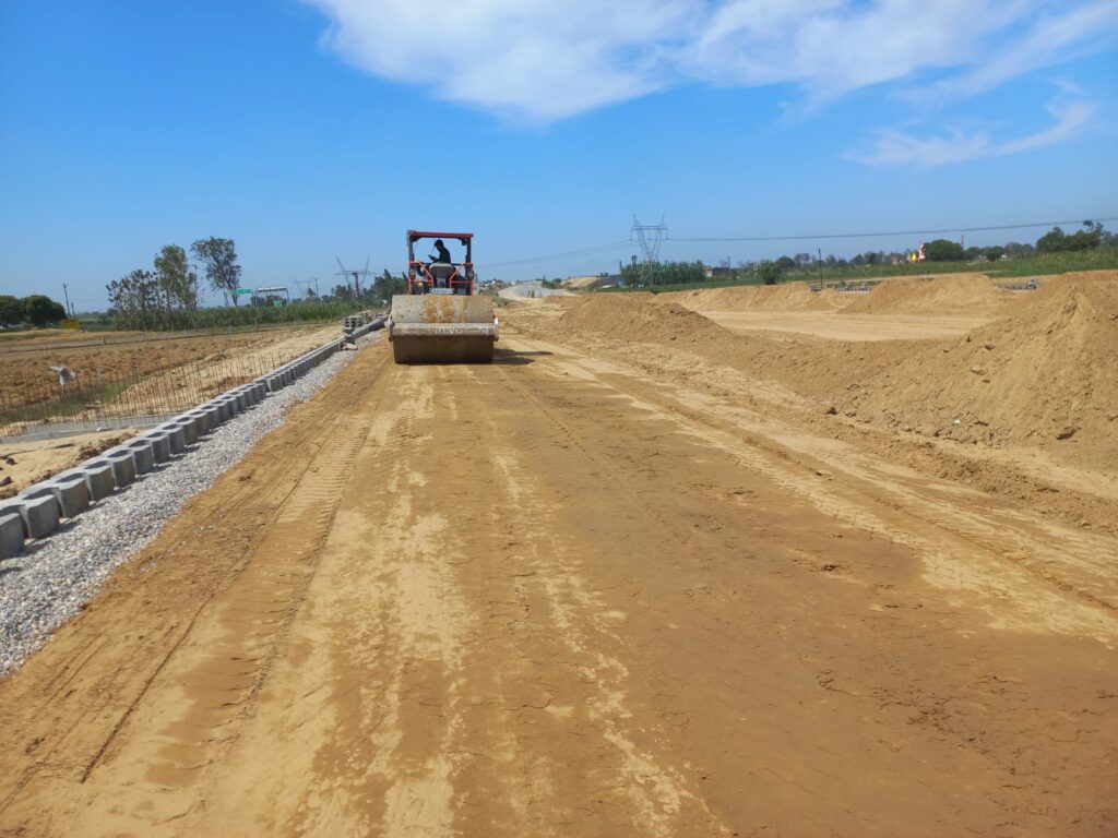
Method Statement for Earthwork (Embankment and Subgrade) Scope This work shall consist of embankment construction with approved material from roadway excavation or borrow pits. Reference IRC:SP:84-2014 MoRTH Specifications, Clause No. 305 IRC:36 Technical Specifications of Contract Equipment Excavator / Backhoe Dozer Motor Grader Dumpers Vibratory Roller Water Tanker Auto Level Measuring Tape Tools Hammer Crow Bar Spade Strings Pegs Lime Powder Manpower & Responsibilities Construction Manager Engineer / Supervisor Land Surveyor Material Engineer Safety Supervisor Helpers Construction Manager He shall be overall responsible for the activity including planning and organizing resources in consultation with the Project Manager. He shall ensure safety requirements, conduct relevant tests, maintain records, and coordinate with the consultant for approvals. Engineer / Supervisor Responsible for deploying resources, executing work as per drawings, maintaining quality as per specifications, and ensuring safety compliance. Also responsible for obtaining necessary approvals. Land Surveyor Responsible for establishing reference points, checking levels and alignment, recording completed work, and coordinating with the consultant for approvals. Material Engineer Responsible for implementing quality procedures, ensuring materials meet specifications, conducting tests, and maintaining records. Safety Supervisor Ensure that all activities are carried out safely as per the project safety plan. Materials Materials shall be free from logs, stumps, roots, rubbish, or any deleterious matter affecting stability. The material shall have: Liquid Limit (LL) less than 55% Plasticity Index (PI) less than 25% Free Swell Index less than 50% Minimum MDD of 15.2 kN/m³ as per IS:2720 Part-8 Samples from borrow areas shall be tested in the laboratory to verify these requirements. Procedures Before commencing earthwork, toe limits of embankment shall be marked. Original ground shall be leveled, scarified, watered, and compacted to achieve 95% of MDD. Material shall be excavated from borrow areas and transported by dumpers. Material shall be spread uniformly using grader/mechanical means. Clods shall be broken to maximum size of 75 mm. If NMC is less than OMC, water shall be added to maintain +1% to -2% of OMC. If NMC is more than OMC, material shall be dried by sun exposure. Compaction shall be done using vibratory roller (80–150 kN) to achieve 95% MDD. Rolling shall start from lower edge to upper edge. Each roller pass shall overlap 1/3rd of the previous pass. Acceptance Criteria Field dry density ≥ 95% of MDD Layer thickness tolerance ±25 mm Moisture content +1% to -2% of OMC during compaction Frequency of Testing Gradation Test (IS 2720 Part-4): 2 tests per 3000 cum Plasticity Test (IS 2720 Part-5): 2 tests per 3000 cum Density Test (IS 2720 Part-8): 2 tests per 3000 cum Deleterious Content (IS 2720 Part-27): As required Moisture Content (IS 2720 Part-2): 1 test per 250 cum CBR Test (IS 2720 Part-16): As required Field Compaction Testing One set of ten density measurements for every 3000 sqm or as required for statistical evaluation. Safety Measures All safety measures shall be followed as per approved EHS Plan. Frequently Asked Questions (FAQ) 1. What is the purpose of embankment construction? Embankment construction is carried out to raise the formation level of the road and provide a stable base for pavement layers. 2. What is the required compaction for embankment? The field dry density should be at least 95% of the Maximum Dry Density (MDD) as per MoRTH specifications. 3. What type of soil is suitable for embankment construction? Soil used should have Liquid Limit less than 55%, Plasticity Index less than 25%, and Free Swell Index less than 50%. 4. What is the optimum moisture condition during compaction? Moisture content should be maintained within +1% to -2% of Optimum Moisture Content (OMC) during compaction. 5. What equipment is commonly used in earthwork? Excavators, dumpers, graders, vibratory rollers, and water tankers are commonly used for embankment and subgrade work. 6. What is the maximum layer thickness allowed? Layer thickness tolerance is generally maintained within ±25 mm as per specifications. 7. Why is CBR testing important? CBR (California Bearing Ratio) test determines the strength of subgrade soil and its suitability for pavement design. 8. How frequently should field density tests be conducted? One set of ten density measurements is carried out for every 3000 sqm of compacted area or as required. 9. What are the key safety measures during earthwork? All activities must follow the approved EHS plan, including use of PPE, proper equipment handling, and safe working practices. 10. What is the role of a surveyor in earthwork? The surveyor establishes reference points, checks alignment and levels, and ensures the work is executed as per design.

Method Statement for Earthwork | Embankment and Subgrade Construction (MoRTH) Read More »

Earthwork

borrow sampling

Borrow Area Method Statement as per MoRTH | QA/QC Construction Procedure

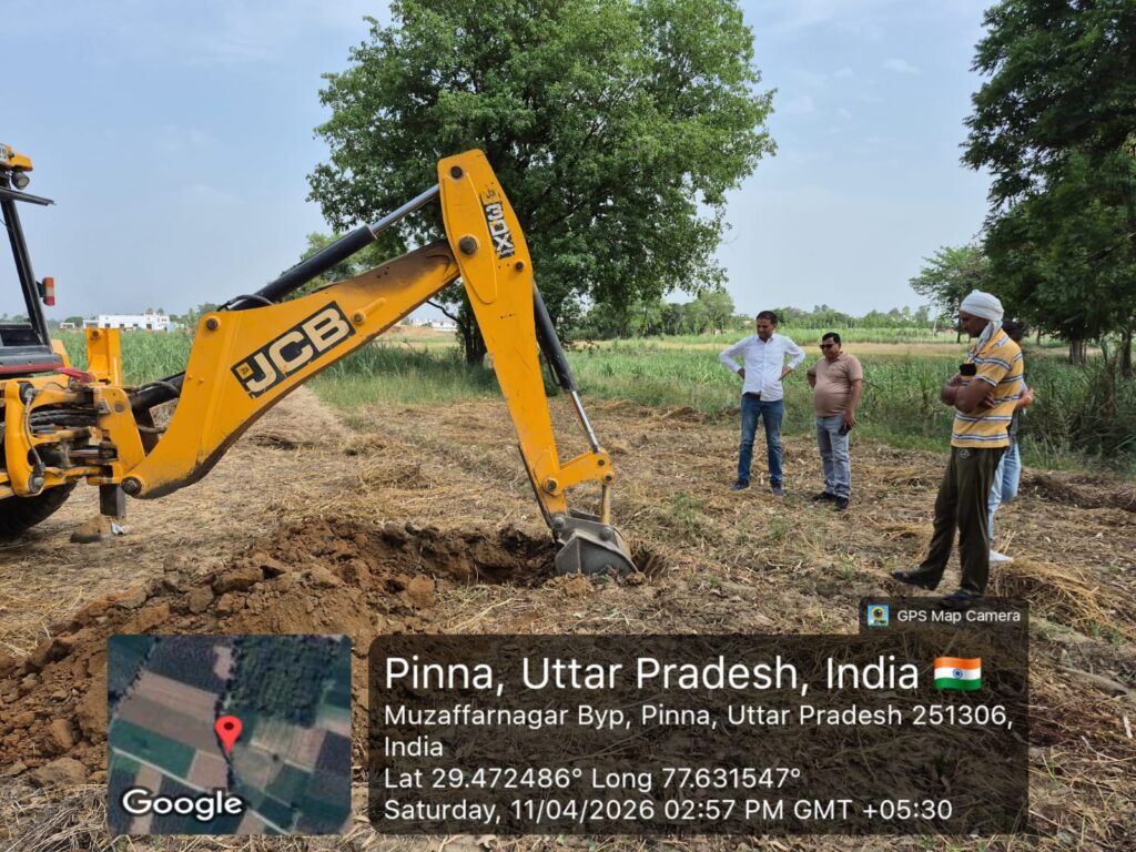
      METHOD STATEMENT FOR BORROW AREA Scope  This method Statement covers the work involved in obtaining borrow Material for work under this contract, including negotiations with owners of the land on which borrow areas are situated, cleaning the site, stripping and disposing of excess overburden, excavating selected material for use in the work, and finishing –off the borrow areas. Reference  MoRT&H Specification clause No 301 to 303 and technical specification of contract Equipment  Excavators, Dumpers Negotiations with owners and authorities  We shall be responsible for all negotiations with and compensation of owners for all borrow area that we shall identify and prescribe. However, for those that are identified are prescribed by the employer consultants, we shall exempted from all obligations and costs in respect of negotiations with and compensations of the owners of the land on which the borrow area situated. Use of Borrow area  Having concluded verbally and in written all the necessary negotiations with the owners of the ground on which any borrow area is situated. We shall open such a borrow area. The notification to the land owners will be at least 7days before prospecting and the engineer will also informed accordingly. Obtaining Borrow area material General  The arrangement for the source of supply of the material for embankment and sub grade and compliance with the guidelines, and environmental requirements, in respect of excavation and borrow area as stipulated from time to time by the ministry of Environmental and forests, government of India and the local bodies, as applicable shall be sole responsibility of the contractor  Borrow pits along the road shall be discouraged. If permitted by the engineer, these shall not be dug continuously. Ridges of not less than 8m width should be left at intervals not exceeding 300m. Small drains shall be cut through the ridges to facilities drainage. The depth of the pits shall be so regulated that their bottom does not cut an imaginary line having a slope of 1 vertical to 4 horizontal projected from the edge of the final section of the bank, the maximum depth in any case being limited to 1.5 m. also, no pits shall be dug within the offset width of a minimum of 10m  Borrow material shall be obtained from approved sources of supply listed and described on the borrow area plans. Or from such other sources as may from time to time be tested and approved by the engineer. Use for Borrow area material  The decision as to which source of supply of borrow material shall be used at any time shall rest with the engineer, and we shall at any stage of work use that approved source of supply which in the opinion of the engineer is the most suitable in regard to the quality and quantities of the various types of available materials and the ultimate cost of the work to the employee.  Should there be need to obtain material from sources other than those shown on the borrow area schedule, we shall excavate the necessary trail holes, and take such samples and conduct or have conducted such tests as are deemed to be necessary by the engineer, we shall submit the results and sufficient details to the engineer to satisfy him that the quality and quality of the material available in the proposed borrow area are acceptable for the intended use, all at our own expense. Compensation to owners and arrangements for taking any material shall be In terms of the project specification.  Approval of borrow area shall apply only to those portions of the area from which acceptable material can be obtained or produced. We shall organelles our operations in any approved borrow area or portions thereof with a view to using the material for the purpose envisaged.  We shall plan our exploitation of the borrow area in such a manner that the various types of materials excavated can be selected and loaded directly for use. When this is unfeasible for reasons beyond our control, material to be stockpiled for later use shall be loaded, transported and temporarily stockpiled as ordered by the engineer and as determined in clause 3203 of SATCC specifications. No material reversed for a specific purpose shall be used for any other purpose without the written approval of the engineer.  Where suitable sources of materials are available in existing cuttings and side drains, or anywhere else in the road prism or within the road reverse boundaries, such material shall be used for the construction of fills, pavement layers and shoulders, if approved by the engineer. Opening and working on Borrow area and Haul Roads Removing topsoil  Prior to opening a borrow area; we shall ascertain from the engineer whether the removal to topsoil is required and shall then remove and stockpile such topsoil as instructed by the engineer. This work shall be carried out, measured and paid for in accordance. Clearing and grubbing  Clearing and grubbing of borrow area will be measured of payment in accordance with the provisions before excavation is commenced, but only in the following cases, unless otherwise directed by the engineer (i) In borrow area located in paginations. (ii) In borrow area where large trees with trunk exceeding 1.0 m in circumference (iii) Borrow area without any excess overburden but where the removal of grass shrubs and roots is required. Unless the cleaning and grubbing of a borrow area have been prescribed by the engineer in writing, no payment will be made for cleaning and grubbing such borrow area. Thos applies practically to borrow areas opened for obtaining rock or sand used in the construction of stone-pitching, concrete work, crushed-stone base or sub-base permeable subsurface drain material or surfacing. Excess overburden  We shall advise the engineer in good time, before any excavation at such borrow area is commenced, of his intension of staffing to use a borrow area in order that a survey of

Borrow Area Method Statement as per MoRTH | QA/QC Construction Procedure Read More »

Soil

Bituminous Concrete (BC) – Profile Corrective Course Construction Methodology

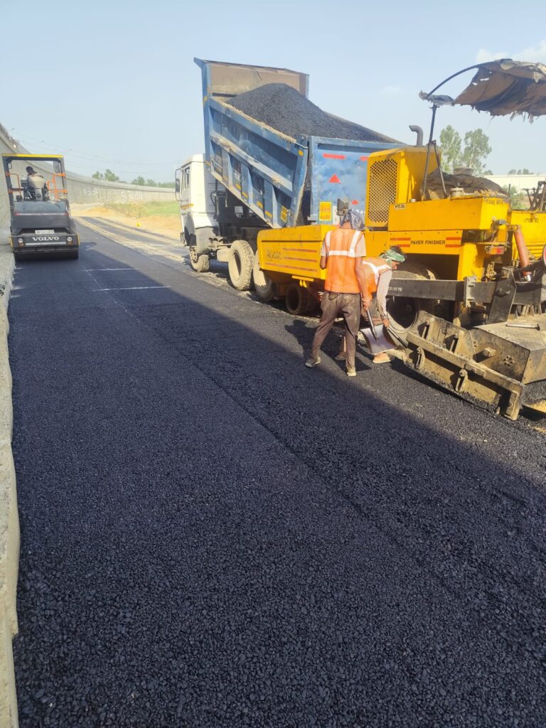
Bituminous Concrete (BC) Profile Corrective Course – Construction Methodology | MoRTH Profile Corrective Course Using Bituminous Concrete (BC) – Construction Methodology Bituminous Concrete (BC) Profile Corrective Course is a thin, dense graded bituminous layer laid to correct minor surface undulations, rutting, shallow depressions and riding quality issues prior to or as part of the final wearing course. 1.0 Scope and Surface Preparation This work consists of providing a Profile Corrective Course using Bituminous Concrete of variable thickness, generally ranging from 30 mm to 50 mm, to restore the pavement profile as per approved longitudinal and cross levels. 1.1 Existing Bituminous Surface Repairs: Potholes, cracks, ravelled areas repaired as per MoRTH Clauses 3004.2 & 3004.3. Milling / Scarifying: Where required, shallow milling carried out to remove surface irregularities. Cleaning: Surface cleaned using mechanical broom and air compressor. Tack Coat: Uniform tack coat applied prior to BC laying. 1.2 Existing Granular Surface (If Applicable) Surface made firm, even and free from loose materials. Priming carried out as per MoRTH Clause 502. Tack coat applied after priming and curing. 1.3 Pre-Laying Level Checks Existing levels shall be checked jointly with Engineer’s representative and recorded to determine thickness and extent of profile correction. 2.0 Plant, Machinery & Equipment Sl. No. Equipment Quantity 1 Batch Type Hot Mix Plant (150–200 TPH) 01 2 Sensor Paver with Electronic Screed Control 01 3 Tandem Vibratory Roller 02 4 Pneumatic Tyred Roller 01 5 Bitumen Pressure Distributor 01 6 Mechanical Broom / Air Compressor 01 7 Tipping Trucks As required 3.0 Materials & Mix Design 3.1 Materials Coarse & fine aggregates conforming to MoRTH Table 500-18 Bitumen: VG-30 / VG-40 / Modified Bitumen (as per contract) Mineral Filler: Cement / Lime / Stone Dust Tack Coat: Rapid Setting Cationic Bitumen Emulsion 3.2 Job Mix Formula (JMF) BC mix design shall be carried out using the Marshall Method as per MoRTH Clause 509. Approved JMF shall specify grading, binder content, temperature limits and target density. 3.3 Hot Mix Plant Operation Bitumen temperature: 150–165°C Aggregate temperature: 150–170°C Mix discharge temperature: 140–165°C Uniform coating ensured with controlled mixing time 4.0 Laying & Compaction 4.1 Transportation of Mix BC mix transported in insulated, tarpaulin-covered trucks. Truck beds coated with approved release agent. Temperature at paver hopper: ≥135°C. 4.2 Tack Coat Application Application rate: 0.20–0.25 kg/m² on bituminous surface. Applied by calibrated mechanical sprayer. Laying commenced only after tack coat breaks. 4.3 Laying & Finishing Sensor wire fixed at 10 m intervals for level control. Minimum laying temperature: 130°C. Loose thickness allowance: approx. 20–25%. Manual finishing permitted in confined or irregular areas. 4.4 Compaction Initial rolling by tandem vibratory roller. Intermediate rolling by PTR. Final finish rolling by static tandem roller. Rolling continued till specified density achieved. Transverse joints cut full depth and edges painted with hot bitumen. 5.0 Quality Control & Traffic Management Core cutting after 24 hours for density verification. Marshall properties verified as per approved JMF. Surface regularity and levels checked as per Clause 902. Traffic opened minimum 24 hours after completion. Traffic diversion with barricades, cones and flagmen. Frequently Asked Questions – BC Profile Corrective Course Purpose of BC PCC? To correct minor profile defects and improve riding quality. Typical thickness? 30–50 mm. Where used? Rutting, shallow depressions, uneven surface. Material? Bituminous Concrete as per MoRTH Clause 509. Tack coat rate? 0.20–0.25 kg/m². Compaction? Tandem roller + PTR. Joint treatment? Full depth cut with hot bitumen painting. Traffic opening? After minimum 24 hours.

Bituminous Concrete (BC) – Profile Corrective Course Construction Methodology Read More »

Bituminous Work

Basic Material Testing Guide for Highway Projects

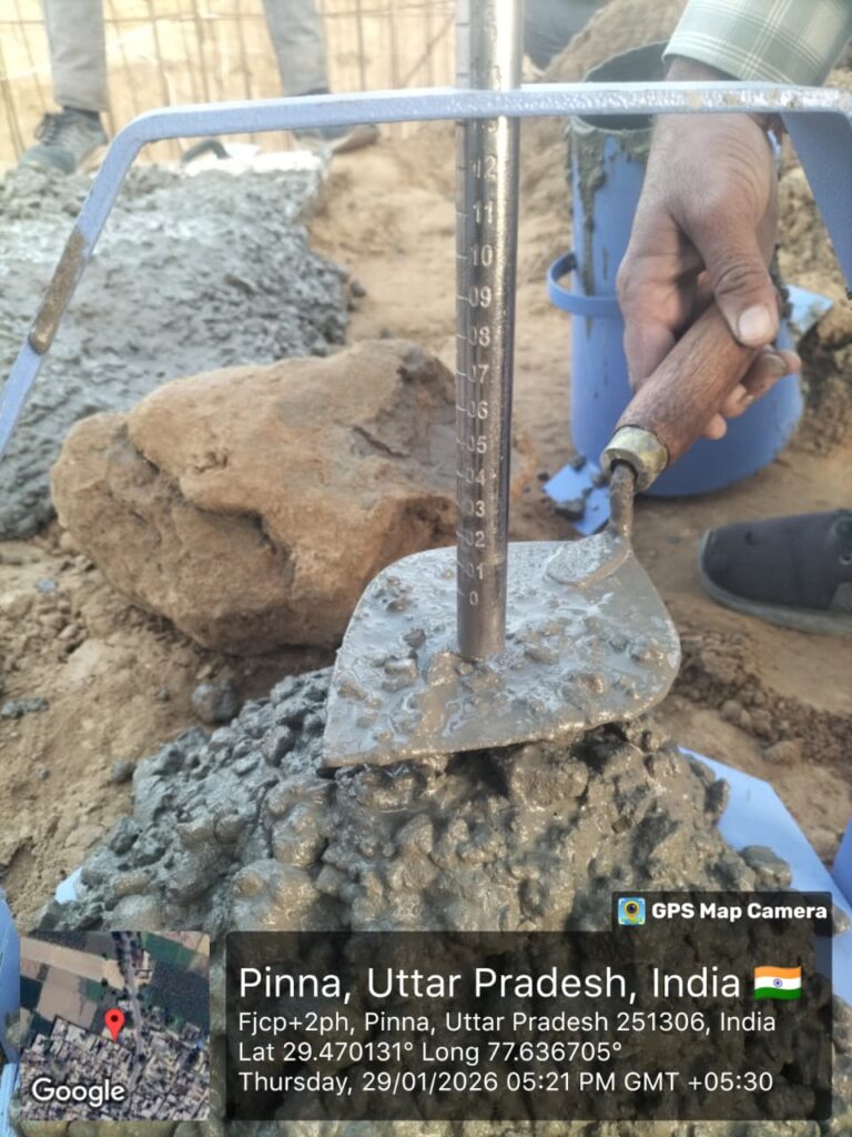
Basic Material Testing Guide for Highway Projects ⚡ Quick Summary ✔ Learn essential material tests ✔ Understand testing purpose ✔ Know key parameters to check ✔ Avoid common site mistakes Material testing is one of the most critical responsibilities of a QA/QC Engineer. The quality of materials directly affects the strength, durability, and performance of a highway. This guide provides a basic overview of the most important tests used on site. 🟤 Soil Testing (Subgrade & Earthwork) Field Density Test (FDT): Ensures proper compaction Moisture Content: Helps achieve optimum density 👉 Key Point: Proper compaction = Strong foundation ⚪ Cement Testing Initial & Final Setting Time: Workability control Fineness Test: Affects strength and hydration 👉 Key Point: Poor cement quality = weak concrete ❌ ⚫ Aggregate Testing Sieve Analysis: Determines grading Impact Value: Measures strength & toughness 👉 Key Point: Proper grading = better load distribution 🛢️ Bitumen Testing Penetration Test: Measures hardness Ductility Test: Measures flexibility 👉 Key Point: Correct grade = longer pavement life ⚠️ Common Testing Mistakes ❌ Wrong sampling method ❌ Skipping test frequency ❌ Uncalibrated equipment ❌ Improper record keeping 💡 Pro Tip: Always follow standard procedures & codes 🎁 Free Download Get Material Testing Formats + Basic Calculators Download Starter Kit 🔒 Want Full Testing Procedures? Unlock step-by-step SOPs, lab methods & Excel tools Upgrade to Pro Bundle

Basic Material Testing Guide for Highway Projects Read More »

FAQ/Interview

Site Documentation Guide for QA/QC Engineers

Site Documentation Guide for QA/QC Engineers ⚡ Quick Summary ✔ Learn essential QA/QC documents ✔ Understand their purpose ✔ Improve site record management ✔ Avoid documentation errors Site documentation is a critical part of quality control in highway projects. Proper records ensure transparency, traceability, and approval of work. Even good quality work can be rejected if documentation is incomplete or incorrect. 📅 Daily Progress Report (DPR) Details of daily work executed Manpower and machinery used Weather conditions Work progress status 👉 Purpose: Track daily site activities and progress 🧱 Cube Test Register Concrete sample details Casting date and location Test results (7 & 28 days) 👉 Purpose: Ensure concrete strength compliance 📦 Material Receipt Register Material quantity and source Approval status Test results and usage 👉 Purpose: Track all incoming materials 📨 Inspection Request (IR) Raised before inspection Submitted to consultant/client Approval required before next activity 👉 Purpose: Get official approval for work execution ⚠️ Common Documentation Mistakes ❌ Missing or incomplete records ❌ Incorrect data entry ❌ Delay in updating registers ❌ No proper approval tracking 💡 Pro Tip: Proper documentation = strong claim & audit support 🔒 Want Editable Excel Formats? Unlock professional templates, auto-calculation sheets & reporting tools Unlock Pro Bundle

Site Documentation Guide for QA/QC Engineers Read More »

FAQ/Interview

Highway Construction Basics (Step-by-Step Guide)

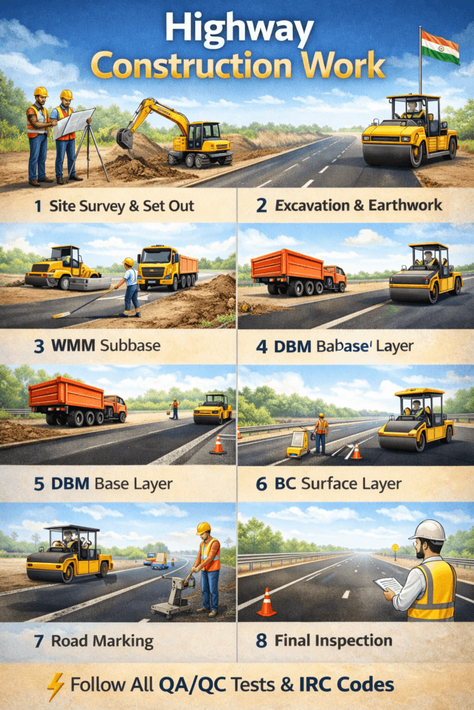
Highway Construction Basics (Step-by-Step Guide) ⚡ Quick Summary ✔ Understand full construction process ✔ Learn layer-wise execution ✔ Know key quality checks ✔ Avoid common site mistakes Highway construction is a systematic process involving multiple layers, each contributing to the strength and durability of the pavement. Proper execution and quality control at every stage are essential to achieve long-lasting performance. 🟤 Step 1: Earthwork (Subgrade Preparation) Clearing & grubbing Excavation or filling Layer-wise compaction 👉 Quality Check: Field Density Test (FDT) 🟫 Step 2: Subgrade Final leveling and dressing Moisture conditioning Compaction as per specification 👉 Key Point: Strong subgrade = strong road foundation 🪨 Step 3: Granular Sub Base (GSB) Material spreading in layers Watering and mixing Rolling and compaction 👉 Quality Check: Gradation + Density 🏗️ Step 4: Wet Mix Macadam (WMM) Mixing in plant Transport to site Laying using paver Compaction with rollers 👉 Quality Check: Thickness + Compaction 🛢️ Step 5: Bituminous Layers Prime coat application Tack coat application Asphalt laying (DBM/BC) 👉 Quality Check: Temperature + Surface finish ⚠️ Common Construction Mistakes ❌ Poor compaction of layers ❌ Incorrect layer thickness ❌ Skipping quality tests ❌ Improper material usage 💡 Pro Tip: Always follow layer sequence + testing requirements 📥 Free Download Get Construction Checklist + QA/QC Formats Download Starter Kit 🔒 Want Full Construction Methodology? Unlock detailed procedures, execution steps & advanced tools Unlock Pro Bundle

Highway Construction Basics (Step-by-Step Guide) Read More »

FAQ/Interview

© 2026 HIGHWAY QUALITY TEST. All rights reserved.

WhatsAppNeed Help?
Scroll to Top