
Fineness of Cement Test as per IS 4031 – Procedure, Formula & Importance
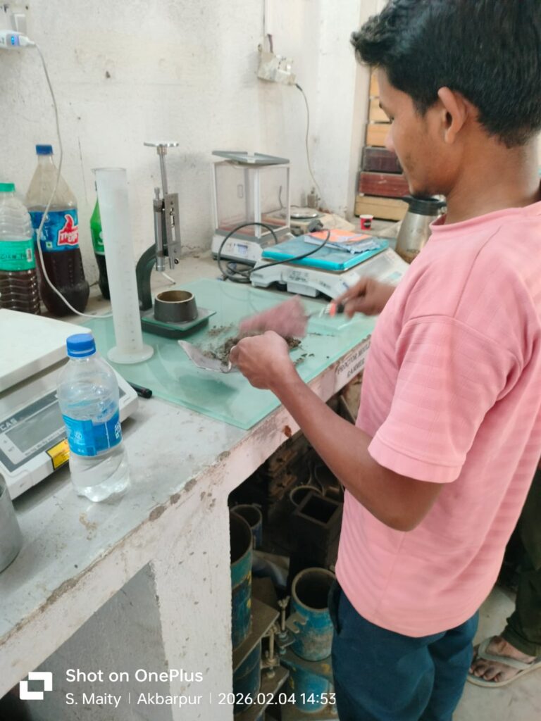
🧪 Determination of Fineness of Cement IS 4031 (Part 3) 🎯 Objective To determine the fineness of cement by dry sieving method using 90 micron IS sieve as per IS 4031 (Part 3). 🛠 Apparatus Required Standard balance with 100 g weighing capacity IS 90 micron sieve Soft sieve brush Cement sample ⚙ Test Procedure Break down any air-set lumps in the cement sample gently with fingers. Accurately weigh 100 g of cement sample. Place the sample on a standard 90 micron IS sieve. 📷 Laboratory Fineness Test of Cement using 90 Micron IS Sieve Continuously sieve the sample for 15 minutes. Collect and weigh the residue retained on the sieve after sieving. 📐 Calculation The percentage residue by weight over the total cement sample is reported as the fineness of cement. % Weight of Residue = (Weight of Sample Retained on Sieve × 100) ———————————————- Total Weight of Cement Sample 📊 Permissible Limits The percentage residue retained on 90 micron sieve should NOT exceed 10%. 💡 Importance of Test Fineness of cement directly affects the rate of hydration, heat generation, setting time, and strength development of concrete. Finer cement provides higher early strength but may increase shrinkage and heat of hydration. This test is essential for NHAI, MoRTH, bridge, highway, and structural QA/QC works. 🧪 IS 4031 • IS 516 • MoRTH • NHAI QA/QC Complete Cement Laboratory Test Series Sequential cement testing procedures performed as per Indian Standard Codes for concrete quality assurance in highway, bridge, rigid pavement, structural, and infrastructure projects. 🔬 IS 4031 (Part 1) STEP 1 Fineness of Cement Determination of cement particle fineness using 90 micron IS sieve and Blaine air permeability method. ⚙️ IS 4031 (Part 4) STEP 2 Standard Consistency Determination of optimum water percentage using Vicat apparatus. ⏱️ IS 4031 (Part 5) STEP 3 Initial Setting Time Measurement of initial hardening stage using Vicat needle penetration. 🧱 IS 4031 (Part 5) STEP 4 Final Setting Time Determines complete hardening stage of cement paste. 📏 IS 4031 (Part 3) STEP 5 Soundness Test Le Chatelier method for determining expansion characteristics of cement. 💪 IS 4031 (Part 6) STEP 6 Compressive Strength Mortar cube compressive strength evaluation at different curing ages. 📌 Quality Control Insight Cement testing must be performed in proper IS code sequence to establish accurate correlation between fineness, consistency, setting characteristics, soundness, and strength development. Sequential testing is mandatory during NHAI, MoRTH, bridge, highway, rigid pavement, and third-party QA/QC inspections.
METHOD STATEMENT FOR OPEN FOUNDATION
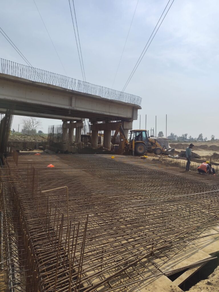
METHOD STATEMENT FOR OPEN FOUNDATION Description The work shall cover furnishing and providing plain or reinforced concrete foundation placed in open excavation, in accordance with the approved drawings and these specifications. Materials Materials shall conform to Section 1000 of these specifications. All materials shall be of approved quality, tested, and conforming to relevant IS and MoRTH requirements before use at site. Preparation of Foundations Excavation for laying the foundation shall be carried out in accordance with MoRTH Clause 300. Open foundations shall be constructed only in dry conditions, and adequate dewatering arrangements shall be provided and maintained throughout the execution of work to ensure a stable and workable foundation bed. Setting Out The plan dimensions of the foundation shall be set out at the bottom of the foundation trench and checked with respect to the original reference line and axis. It shall be ensured that at no point the bearing surface is higher than the founding level shown on the drawing. Safe Bearing Capacity (SBC) of Soil As per the drawing requirements, the Safe Bearing Capacity (SBC) of the foundation soil shall be ensured before commencement of the work by the in-house QC laboratory. All results shall be verified and approved prior to execution. Construction Where the bearing surface is earth, a layer of M15 concrete shall be provided below the foundation concrete. The minimum thickness of the lean concrete layer shall be 150 mm unless otherwise specified. No formwork is required for the lean concrete layer. For foundation concrete work, side formwork shall be used. Formwork for the top of foundation concrete shall also be provided if the top has slopes steeper than 1 (vertical) to 3 (horizontal). When concrete is laid on a slope without top formwork, the slump shall be carefully controlled to ensure proper compaction without slippage of freshly placed concrete. In certain cases, it may be necessary to construct the top formwork progressively as concreting proceeds up the slope. Reinforcement shall be placed strictly as shown in the approved drawings. Before laying the lean concrete layer, the earth surface shall be thoroughly cleaned of all loose material and properly wetted. Care shall be taken to avoid muddy conditions. If any portion of the surface is found spoiled due to over-wetting, the same shall be removed and re-prepared before concreting. Inspection Plan and Testing S.No Activity Inspection Required Tests Required Remarks 1 Approval of Previous Element of Structure Yes Yes Jointly recorded 2 Layout & Survey Yes — Joint survey and record 3 Formwork & Reinforcement Check Yes Yes Jointly recorded 4 Concreting Yes — Method control 5 Strength Check Yes Yes QC check jointly Safety Measures ✔ All safety measures shall be strictly implemented as per the approved EHS (Environment, Health & Safety) Plan.
Method Statement for Dismantling Culverts, Bridges, Pavements and Other Structures
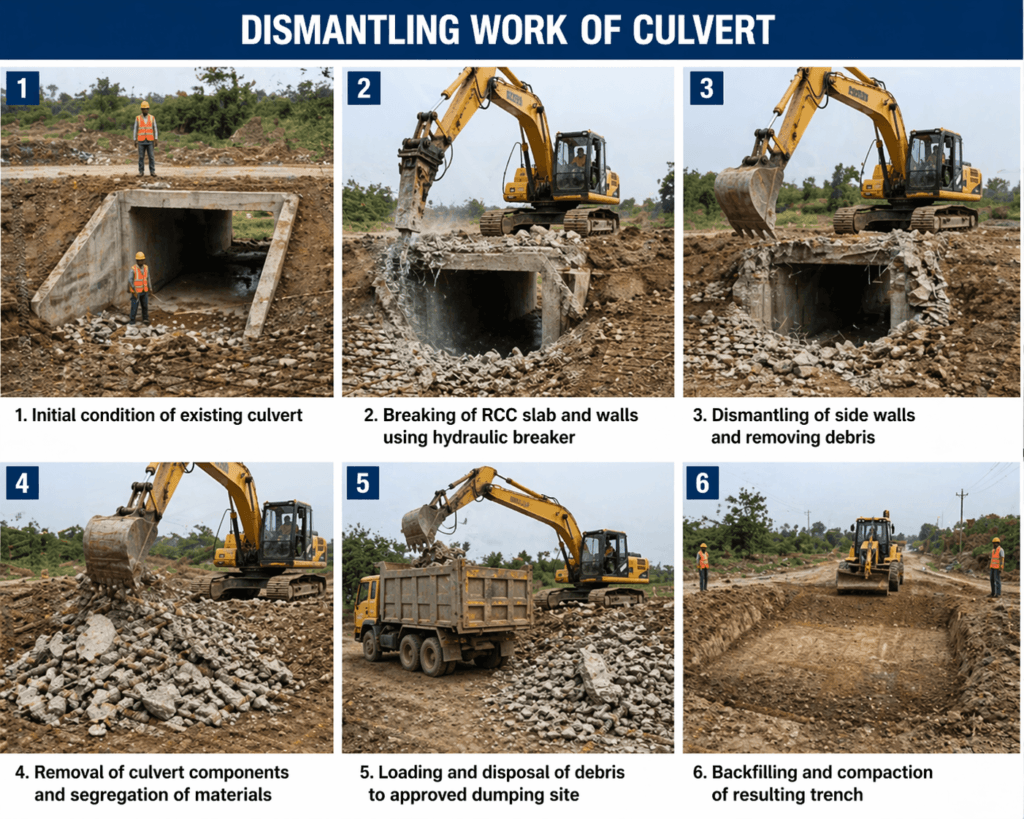
Method Statement for Dismantling Culverts, Bridges, Pavements and Other Structures [last_updated] 1. Purpose The purpose of this Method Statement is to define the detailed construction methodology for dismantling culverts, bridges, pavements, kerbs, and other structures in accordance with the provisions of MoRTH Clause 202 and relevant amendments in the Technical Specifications. 2. Scope of Work The work shall consist of removing existing culverts, bridges, pavements, kerbs, and other structures that interfere with new construction activities or are unsuitable to remain in place. The work shall also include salvaging, disposal of dismantled materials, and backfilling of resulting trenches and pits. Existing structures located within the highway limits and designated for removal shall be dismantled up to the extent shown in the Good for Construction (GFC) drawings or as directed by the Authority Engineer. Dismantling operations shall be carried out using suitable equipment such as backhoe loaders, excavators, dozers, graders, tractor dozers, jackhammers, or excavators fitted with rock breakers, depending upon the type of structure. Care shall be taken to avoid disturbance or damage to adjacent pavements, structures, underground utilities, and any work intended to remain in place. All dismantling operations that may affect new construction shall be completed before commencement of new works. Traffic diversion, safety arrangements, and traffic management measures shall be implemented as per approved methodology prior to dismantling activities. Dismantling work shall commence only after obtaining approval from the Authority Engineer. 3. Sequence of Operations 3.1 Dismantling of Culverts and Bridges Existing culverts and bridges shall be dismantled carefully to prevent damage to reusable materials, portions of structures to be retained, nearby properties, and adjacent structures. Where existing culverts or bridges are to be extended or incorporated into the new work, only the required portion shall be removed as directed by the Authority Engineer. Connecting edges shall be cut, chipped, and trimmed to the required alignment and levels without weakening the remaining structure. Reinforcement bars intended for future connection as dowels or ties shall be protected from damage during dismantling operations. Pipe culverts shall be dismantled carefully to avoid breakage or damage to the pipes. 3.2 Dismantling of Pavements and Other Structures Existing pavements, kerbs, gutters, and other structures shall be dismantled as specified in the drawings and Technical Specifications. Portions intended to remain in service shall be cut neatly along straight lines or existing joints with faces perpendicular to the pavement surface. Sufficient dismantling shall be carried out to achieve proper grades, alignment, and connection with the proposed works. Concrete pavements, bituminous pavements, shoulders, and base courses designated for dismantling shall be broken into pieces not exceeding 0.02 cubic metres. Dismantled materials shall either be stockpiled at approved locations for reuse or disposed of as directed by the Authority Engineer. Holes, depressions, and excavated areas resulting from dismantling operations shall be backfilled using approved material and compacted to the specified density. Disposal of dismantled materials shall be carried out in accordance with the relevant Technical Specifications and environmental requirements. 4. Equipment Used Backhoe Loader Excavator Bull Dozer Tractor Dozer Motor Grader Jack Hammer Excavator with Rock Breaker
Soundness Test of Cement – Le Chatelier Method
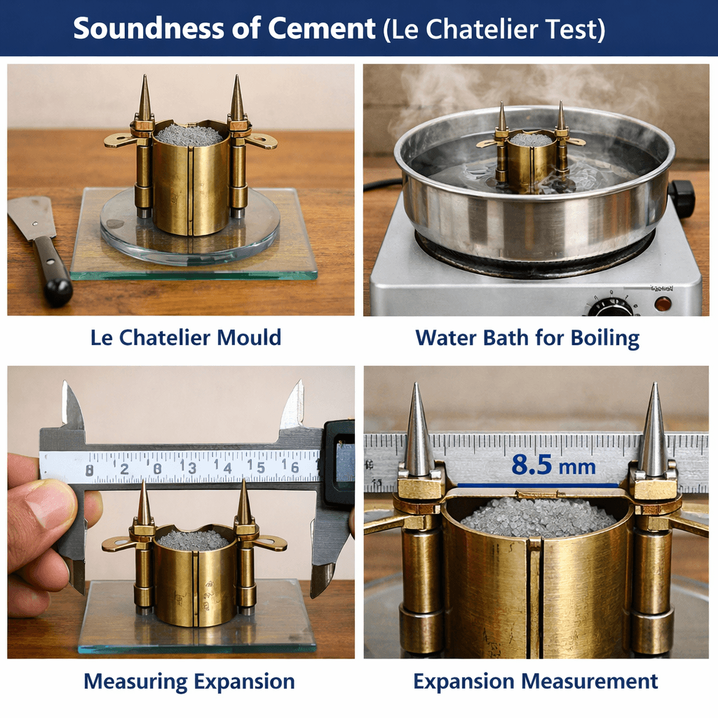
Soundness Test of Cement – Le Chatelier Method Author: Kishor Kumar · Updated: February 2026 · Read time: ~8 minutes 1. Introduction The Soundness Test of Cement ensures that cement does not undergo excessive expansion after setting, which can cause cracks in concrete and structural failure. The Le Chatelier Method specifically measures expansion due to free lime (CaO) or magnesia content. 2. Purpose Check dimensional stability of cement Detect presence of free lime (CaO) or magnesia Prevent cracking in concrete structures Ensure compliance with IS 4031 Part 3 and MoRTH specifications 3. Applicable Standards IS 4031 (Part 3) – Soundness test of cement using Le Chatelier method IS 4031 (Part 4) – Standard consistency for paste MoRTH Specifications – Cement quality control 4. Apparatus Le Chatelier Mould (split ring, inner & outer arcs) Vernier Caliper – for measuring expansion Water Bath / Beaker – 27–30°C Glass Plate / Base Plate Mortar Preparation Tools (trowel, spatula) 5. Test Sample Preparation Cement paste is prepared using standard consistency water. Example ratio: 1 part cement : 0.78 parts water (by weight). Sample Preparation Example: For 100 g of cement: Water required = 100 × 0.78 = 78 g Mix cement and water to obtain a uniform paste for filling the Le Chatelier mould. 6. Test Procedure – Le Chatelier Method Preparation of Cement Paste Determine the standard consistency of cement using IS 4031 (Part 4). Mix cement and water (~1:0.78 by weight) to obtain uniform paste. Avoid lumps to ensure accurate test results. Filling the Le Chatelier Mould Clean mould thoroughly and lightly oil to prevent sticking. Fill mould carefully, avoiding air pockets. Tap gently or use spatula to compact paste evenly. Leveling the Paste Level top of paste to match upper rim of mould. Ensure flush surface to avoid erroneous readings. Immersion in Water Bath Place mould in water bath maintained at 27–30°C for 24 hours. Keep undisturbed and maintain constant temperature. Measurement of Expansion Remove mould carefully after 24 hours. Measure distance between indicator arms using vernier caliper. Take measurements to nearest 0.5 mm for precision. Calculation of Expansion Formula: Expansion (mm) = Final distance between arms – Original distance between arms Record mean of two measurements if multiple moulds are tested for accuracy. 7. Acceptance Criteria Maximum expansion for OPC: ≤ 0.8 mm (IS 4031 Part 3) Rapid Hardening Cement: slightly lower limits 8. Engineering Significance Prevents cracks in concrete due to excessive expansion Ensures dimensional stability of cement in structural and pavement applications Critical for highway pavements, bridges, and high-rise concrete structures 9. Common Mistakes Air bubbles while filling mould Incorrect water bath temperature Improper vernier caliper measurement Using non-standard consistency paste Ensure proper handling to avoid false readings; repeat test if inconsistent. 10. Frequently Asked Questions What is the purpose of the Le Chatelier test? It checks cement expansion due to free lime or magnesia, ensuring dimensional stability. Which IS code covers the test? IS 4031 (Part 3) What is the maximum allowable expansion? ≤ 0.8 mm for Ordinary Portland Cement (OPC) How is cement paste prepared? Using standard consistency water; example ratio: 1 part cement : 0.78 parts water by weight. What happens if expansion exceeds the limit? Excessive expansion indicates free lime; cement should be rejected or used with caution in structural work. 11. Conclusion The Soundness Test of Cement – Le Chatelier Method ensures cement stability, prevents cracks, and guarantees compliance with IS 4031 and MoRTH specifications. Always perform this test for critical concrete and pavement works. Written by: Kishor Kumar · Civil / Highway Engineer – QA/QC & Site Execution · Source: HighwayQualityTest.com 🧪 Complete Cement Laboratory Test Series IS 4031 IS 516 MoRTH NHAI QA/QC These laboratory tests are conducted sequentially for complete cement and concrete quality verification in highway, bridge, structure, and rigid pavement works as per IS 4031, IS 516, MoRTH Specifications, and NHAI Quality Assurance Protocols. 🔬 Fineness of Cement IS 4031 (Part 1) Sieve analysis and Blaine air permeability method for determining cement particle fineness. ⚙️ Standard Consistency IS 4031 (Part 4) Determination of optimum water percentage using Vicat apparatus. ⏱️ Initial Setting Time IS 4031 (Part 5) Measures the beginning of cement hardening using Vicat needle penetration. 🧱 Final Setting Time IS 4031 (Part 5) Determines the complete hardening stage of cement paste. 💪 Compressive Strength IS 4031 (Part 6) Mortar cube crushing strength evaluation at different curing ages. 🏗️ Concrete Cube Test IS 516 Concrete compressive strength testing for site quality control and mix validation. 📌 Quality Control Insight These tests must be conducted in proper sequence to establish correlation between cement fineness, water demand, setting characteristics, and strength development during highway, bridge, and structural concrete works—especially under NHAI, MoRTH, and independent third-party QA/QC audits.
Final Setting Time of Cement
Final setting time is the time taken by cement paste to completely lose plasticity and attain hardness. As per IS 4031, it should not exceed 600 minutes for OPC.
Compressive Strength of Cement
Compressive Strength Test of Cement Mortar Cubes – IS 4031 (Part 6) | Step-by-Step with Examples Compressive Strength Test of Cement Mortar Cubes (IS: 4031 – Part 6) Quick Summary: IS:4031 (Part-6) specifies the method for determination of compressive strength of cement using standard mortar cubes of size 70.6 mm. Cubes are prepared in a 1:3 cement–standard sand mix, compacted by vibration, cured for 3, 7 and 28 days, and tested at a loading rate of 35 N/mm²/min. The test ensures that cement meets the minimum strength requirements prescribed for OPC-43 and OPC-53 grades. See calculation & examples → Example: This test is used to check whether an OPC 43 or OPC 53 cement bag supplied to site meets BIS strength requirements at 3, 7 and 28 days. 1. Intoduction: To determine the compressive strength of hydraulic cement, standard cement mortar cubes (70.6 mm size) are cast and compacted using a standard vibration machine as per IS 4031 (Part 6). This Compressive Strength Test ensures cement quality by covering cube casting, curing, testing, calculation, and result interpretation, making it field-ready for engineers and QA/QC teams to ensure reliable concrete performance in highway and structural applications. 2. Apparatus Vibration machine (12,000 ± 400 vibrations/min) Cube moulds – 70.6 mm × 70.6 mm × 70.6 mm Standard sand (IS 650 : 1966) Prodding rod Non-porous mixing plate Weighing balance Cube crushing testing machine (CTM) Mould oil, petroleum jelly Potable / distilled water Example: If your CTM capacity is 2000 kN and vibration machine speed is calibrated annually, the setup satisfies IS requirements. 3. Standard Sand (IS 650) Particle Size Range Percentage 2.0 mm – 1.0 mm 33.33% 1.0 mm – 500 micron 33.33% 500 micron – 90 micron 33.33% Example: If 900 g of standard sand is tested for gradation, each fraction should weigh approximately 300 g. 4. Mix Proportion Material Quantity Cement 200 g Standard Sand 600 g Water (P/4 + 3)% P = % water required for standard consistency (IS 4031 Part 4) Example: If standard consistency P = 26% Water = (26/4 + 3)% = 9.5% Total mass = 800 g Water = 0.095 × 800 = 76 g 5. Mixing Procedure Dry mix cement + sand for 1 minute. Add calculated water. Mix for minimum 3 minutes. Reject mix if uniform colour is not achieved within 4 minutes. Example: Dry mixing from 10:00–10:01 AM Wet mixing ends at 10:04 AM → ACCEPTABLE If mixing continues beyond 10:05 AM → REJECT batch 6. Moulding of Specimens Oil mould and base plate. Fix mould firmly on vibration table. Fill mortar in layers. Prod each layer 20 times in ~8 seconds. Vibrate for 2 minutes. Finish surface using trowel. Example: 1st layer: 20 rod blows in 8 s 2nd layer: 20 rod blows in 8 s Vibration time: 2 minutes exactly 7. Curing of Specimens Keep moulds in moist room for 24 hours. Demould and immerse in water. Maintain water temperature at 27 ± 2°C. Renew water every 7 days. Example: Casting completed at 4 PM on Day-0 Demould at 4 PM on Day-1 3-day test conducted at 4 PM on Day-3 8. Testing of Specimens Test cubes on their sides. Load rate: 35 N/mm² per minute. Test minimum three cubes. Example: For cube area 50 cm² (=5000 mm²), Load rate ≈ 175 kN per minute 9. Calculation of Compressive Strength Compressive Strength = P / A Example (kg-machine): Crushing load = 7200 kg Area = 50 cm² Strength = 7200 / 50 = 144 kg/cm² Example (kN-machine): Load = 720 kN Equivalent load = 720 × 101.97 = 73418 kg Strength = 73418 / 50 = 1468 kg/cm² 10. Minimum Strength Requirements OPC 43 Grade Cement Age Strength (MPa) kg/cm² 3 Days 23 235 7 Days 33 337 28 Days 43 438 OPC 53 Grade Cement Age Strength (MPa) kg/cm² 3 Days 27 275 7 Days 37 377 28 Days 53 540 ⬇ Download Cement Mortar Cube Test – Excel Sheet Top 10 FAQs – Compressive Strength of Cement What is the compressive strength of cement? It is the maximum load per unit area that a cement mortar cube can withstand under compression. Which IS code governs the compressive strength test of cement? IS:4031 (Part-6) specifies the procedure for determination of compressive strength of cement. Why is standard sand used in cement strength testing? Standard sand (IS:650) ensures uniform grading and repeatable test results. What is the size of cement mortar cube? Standard cube size is 70.6 mm × 70.6 mm × 70.6 mm with a cross-sectional area of 50 cm². What is the mix proportion for cement mortar cubes? Cement : Standard Sand = 1 : 3 by weight. How is water quantity calculated? Water = (P/4 + 3)% of the combined weight of cement and sand, where P is the standard consistency. What are standard curing periods? Cement mortar cubes are tested at 3 days, 7 days, and 28 days. What is the required compressive strength for OPC cement? OPC-43: 23, 33, 43 MPa and OPC-53: 27, 37, 53 MPa at 3, 7, and 28 days respectively. How is compressive strength calculated? Strength (kg/cm²) = Crushing Load (kg) / Area (cm²). Can a compression testing machine display load in kN? Yes. Load in kN must be converted into kg before calculating strength. Prepared by Kishor Kumar | Source: HighwayQualityTest.com Standard Reference: IS 4031 (Part 6) – Methods of Physical Tests for Hydraulic Cement (BIS). Quick Reference: Compressive Strength of Cement (IS:4031 Part-6) Test Objective: Determine compressive strength of standard cement mortar cubes Specimen Size: 70.6 mm × 70.6 mm cube (area = 50 cm²) Mix Proportion: Cement : Standard Sand = 1 : 3 by weight Quantity per Cube Set: Cement = 200 g, Sand = 600 g Water Content: (P/4 + 3)% of combined mass of cement and sand Standard Sand: Conforming to IS:650 (100% passing 2 mm, retained on 90 micron) Compaction: Vibration for 2 minutes @ 12,000 ± 400 vibrations/min Curing Periods: 3 days,
PQC Methodology
Pavement Quality Concrete (PQC) M40 – Complete Construction & QA/QC Guide Pavement Quality Concrete (PQC) M40: Complete Construction & QA/QC Guide Pavement Quality Concrete (PQC) of M40 grade forms the structural load-bearing layer in rigid pavements of National Highways. This guide provides a detailed overview of materials, mixing, placement, curing, joint detailing, dowel and tie bar installation, and quality assurance/quality control (QA/QC) procedures. It also highlights common issues, their solutions, and aligns with MoRTH Section 602 and IRC standards. For more insights, see the main pillar page on Rigid Pavement Components. Applicable Standards Reference Documents S. No. Document Description 1 Contract Agreement 2 IRC: SP: 84-2014 3 Ministry of Road Transport & Highways Specifications (MoRTH – 5th Revision) 4 Relevant Drawings 1. Understanding PQC PQC is a high-strength concrete layer designed to transfer traffic loads directly to the subgrade through slab action. It is especially suited for highways with heavy traffic, high axle loads, and long-term durability requirements. Benefits of PQC include: Exceptional flexural strength and load transfer capacity Durable surface resistant to rutting and deformation Expected service life of 30–40 years Reduced long-term maintenance requirements Resistance against oil, water, and temperature-induced damage 2. Material Specifications for M40 PQC Materials 1. Source of Materials The Contractor shall indicate to the AE the source of all materials to be used in the concrete work with relevant test data sufficiently in advance. 2. Cement Any of the following types of cement capable of achieving the design strength may be used: S. No. Type of Cement Conforming To 1 OPC 43 / OPC 53 Grade IS:269 2 Portland Slag Cement IS:455 3 Portland Pozzolana Cement IS:1489 (Part-I) 3. Admixtures a. Chemical Admixtures Admixtures conforming to IS:9103 and IS:6925 shall be permitted to improve workability of concrete or extension of setting time, on satisfactory evidence that they will not have any adverse effect on the properties of concrete with respect to strength, volume change, durability and shall have no deleterious effect on steel bars. b. Mineral Admixtures Fly ash up to 20% by weight of cementitious material may be used in Ordinary Portland Cement 43 or 53 Grade as part replacement of cement provided uniform blending with cement is ensured. The fly ash shall conform to IS:3812 (Part-I) and GGBFS shall conform to IRC:15-2017 / IS:16714-2018. Site mixing of fly ash shall be permitted ensuring availability of equipment at site for uniform blending through specific mechanized facilities with automated process control like batch mix plants conforming to IS:4925 and IS:4926. 4. Aggregate Aggregates for pavement concrete shall be natural material complying with IS:383 but with Los Angeles Abrasion Test value not exceeding 35 percent. The limits of deleterious materials shall not exceed the requirements set out in Table 600-2 of MoRTH Specifications. a. Coarse Aggregate The maximum size of coarse aggregate shall not exceed 31.5 mm for pavement concrete. The Los Angeles Abrasion Value shall not exceed 35. The combined flakiness and elongation index of aggregate shall not be more than 35 percent. b. Fine Aggregate The fine aggregate shall consist of clean natural sand or crushed stone sand or a combination of the two and shall conform to IS:383. The fine aggregates shall have a sand equivalent value of not less than 50 when tested in accordance with IS:2720 (Part-37). c. Combined Gradation of Fine and Coarse Aggregate The combined gradation of fine and coarse aggregates shall be as per Table 600-3 of MoRTH Specifications. 5. Water Water used for mixing and curing of concrete shall be clean and free from injurious amounts of oil, salt, acid, vegetable matter and other substances harmful to the finished concrete. 6. Steel for Dowels and Tie Bars Steel shall conform to the requirements of IS:432 and IS:1786 as relevant. Dowel bars shall conform to IS:432 of Grade-I. Tie bars shall be either High Yield Strength Deformed bars conforming to IS:1786 and Grade Fe-500 or plain bars conforming to IS:432 of Grade-I. Steel shall be coated with epoxy paint for protection against corrosion. 7. Joint Filler Board Synthetic joint filler board for expansion joints shall be used only at abutting structures like bridges and shall be of 20–25 mm thickness with a tolerance of ±1.5 mm and of firm compressible material complying with IS:1838, having compressibility more than 25%. 8. Joint Sealing Compound The joint sealing compound shall be of hot poured elastomeric type or cold polysulphide/polyurethane/silicone type having flexibility, resistance to age hardening and durability as per IRC:57. 9. Preformed Seals The pre-formed sealing material shall be vulcanized elastomeric compound using polychloroprene (Neoprene) as the base polymer. 10. Storage of Materials All materials shall be stored in accordance with the provisions of Clause 1014 of MoRTH Specifications. Proportioning of Concrete 1. Cement Content The quantity of cement shall not be less than 360 kg/cu.m for all types of cement. In case Fly Ash Grade-I (as per IS:3812) is blended at site as part replacement of cement, the quantity of fly ash shall be up to 20% by weight of cementitious material and the quantity of OPC in such blend shall not be less than 310 kg/cu.m. If GGBFS is used, minimum OPC content shall not be less than 310 kg/cu.m. 2. Concrete Strength The characteristic flexural strength of concrete for 28 days shall not be less than 4.5 MPa unless specified otherwise. Target mean flexural strength for mix design shall be: 4.5 MPa + 1.65s Where “s” is the standard deviation of flexural strength derived by conducting tests on minimum 30 beams. The water content shall be the minimum required to provide the agreed workability for full compaction of concrete to the required density as determined by trial mixes. The maximum free water cement ratio shall be: 0.45 when only OPC is used 0.50 when blended cement (PPC / PSC / OPC blended with Fly Ash or GGBFS) is used IRC:44 shall also be referred regarding selection of water-cement ratio. The ratio between the 7-day and 28-day strength shall be established for the mix to
Compressive Strength of Concrete Cube Test (IS 516 Guide)
Concrete Cube Test – IS 516 Procedure, Compressive Strength & Formula 1. Objective The Concrete Cube Test as per IS 516 is the standard method used to determine the compressive strength of concrete for pavements, buildings, bridges, and structural elements. It verifies whether the concrete supplied at site meets the specified grade requirements and ensures structural safety and durability. This test involves preparing, casting, curing, and testing concrete cube specimens of size 150 × 150 × 150 mm or 100 × 100 × 100 mm to determine compressive strength at specified ages — typically 7 days (early strength assessment) and 28 days (characteristic strength verification). The procedure includes: Proper mould preparation and oiling Sampling of fresh concrete as per standard practice Layer-wise filling and compaction (tamping/vibration) Initial setting period and demoulding after 24 ± ½ hours Water curing under controlled temperature conditions Compression testing using a calibrated Compression Testing Machine (CTM) Calculation of compressive strength (Load / Cross-sectional Area) Accurate execution of cube testing ensures: Verification of concrete grade (M20, M25, M30, etc.) Early detection of batching or mix design issues Compliance with project specifications and quality control norms Long-term durability and structural performance Designed for site engineers, QA/QC teams, laboratory technicians, and project managers, this guide provides practical, step-by-step instructions to ensure reliable results and compliant construction practices. 2. Apparatus Required Cube moulds – 150 mm or 100 mm Mixing tray and scoop Tamping rod (16 mm diameter) Trowel Concrete mixer (if required) Curing tank (27 ± 2°C) Compression Testing Machine (CTM) 3. Preparation of Cube Moulds Clean moulds to remove dust and hardened mortar. Assemble moulds properly and tighten bolts. Apply thin uniform oil layer on internal faces. Check alignment and squareness of mould. 4. Sampling and Mixing of Concrete Sample concrete from freshly mixed batch. Mix thoroughly until uniform colour and consistency are achieved. Start casting immediately to avoid loss of workability. 5. Casting of Concrete Cubes Fill mould in three equal layers. Distribute concrete evenly around mould. 6. Compaction of Concrete Compact each layer by rodding or vibration. Manual compaction: 35 strokes per layer. Rods to penetrate into the previous layer. Tap mould sides gently to remove air voids. Finish top surface smoothly using trowel. 7. Identification and Initial Storage Date of casting Grade of concrete Cube number / location Store cubes undisturbed for 24 hours at 27 ± 2°C. 8. Curing of Concrete Cubes Demould cubes after 24 ± ½ hours. Immediately immerse in clean water. Maintain curing temperature at 27 ± 2°C. Continue curing till testing age. 9. Compression Testing of Cubes (IS:516) Remove cube from curing tank (SSD condition). Clean cube and CTM platens. Measure dimensions (nearest 0.2 mm). Place cube centrally on CTM platen. Apply load gradually at ≈140 kg/cm²/min. Record maximum load at failure. Note: Improper centring causes eccentric loading and wrong test results. 10. Calculation of Compressive Strength Compressive Strength (N/mm²) = Maximum Load at Failure ÷ Loaded Area 11. Cube Size – Area – Thumb Rules Cube Size Loaded Area 150 mm Cube 225 cm² 100 mm Cube 100 cm² Fast Site Calculation Rules 150 mm cube → Load (kg) ÷ 225 | Load (kN) ÷ 22.5 100 mm cube → Load (kg) ÷ 100 | Load (kN) × 10 12. Sampling Frequency (IS Practice – Simplified) Concrete Quantity No. of Samples Total Cubes 1 – 5 m³ 1 3 6 – 15 m³ 2 6 16 – 30 m³ 3 9 31 – 50 m³ 4 12 Each additional 50 m³ +1 +3 13. Reporting of Results Calculate strength of each cube. Round off to nearest whole number. Average of 3 cubes = representative strength. Variation limits must be satisfied. Concrete Strength Acceptance Criteria (±15% Rule Explained) Basic Rule For any set of 3 cubes (one sample): Calculate average strength Each cube must lie within: 0.85 × Average (−15%) 1.15 × Average (+15%) If even one cube is outside this range, the sample is REJECTED, irrespective of average strength. Key Strength Values – M25 Concrete Characteristic strength (fck) = 25 N/mm² Standard deviation (assumed) = 4 N/mm² Target mean strength = fck + 1.65 × S = 25 + (1.65 × 4) = 31.6 N/mm² CASE–1: Single Sample (Small Quantity Concrete) Concrete Quantity = 5 m³ As per IS practice → 1 sample (3 cubes) Acceptance Criterion (Special Case) When only one sample is available: Average strength ≥ fck + 4 = 29 N/mm² Cube Strengths (N/mm²) Average 0.85 × Avg 1.15 × Avg 19, 26, 16 20.3 17.3 23.3 Reasons for Rejection ❌ Average strength less than 29 N/mm² ❌ Cubes 26 and 16 N/mm² outside ±15% range Final Decision: ❌ CONCRETE REJECTED CASE–2: Multiple Samples (Normal Quantity Concrete) Concrete Quantity = 28 m³ Samples required = 3 samples (9 cubes) Acceptance Criteria Each cube ≥ fck − 2 = 23 N/mm² Overall average ≥ fck + 4 = 29 N/mm² ±15% variation satisfied for each sample Sample-wise Results Sample Cube Strengths (N/mm²) Average 0.85 × Avg 1.15 × Avg 1 33, 29, 32 31.3 26.6 36.0 2 24, 32, 28 28.0 23.8 32.2 3 25, 29, 32 28.7 24.4 33.0 Overall Average Strength (31.3 + 28.0 + 28.7) ÷ 3 = 29.3 N/mm² Acceptance Check (As per IS Acceptance Criteria) ✅ ±15% Variation Check: All individual cube strengths fall within the permissible range of 0.85 × Average to 1.15 × Average for their respective samples. This confirms uniformity in batching, mixing, compaction, and curing of concrete. ✅ Minimum Individual Strength Check: Each tested cube has achieved a compressive strength greater than or equal to fck − 2, i.e. 23 N/mm² for M25 concrete. No cube strength is below the minimum permissible limit. ✅ Average Strength Check: The overall average compressive strength of all samples is 29 N/mm² or higher, which satisfies the requirement of fck + 4 for acceptance of concrete under normal sampling conditions. ✅ Quality and Compliance Confirmation: Since variation, individual strength, and average strength criteria are all satisfied, the concrete meets the
Dry Lean Concrete (DLC) Methodology | Highway Construction Guide
The work shall consist of construction of dry lean concrete subbase forcement concrete pavement in accordance with the requirements of these specificationsand in conformity with the lines,
Methodology for Kerb Casting

This method statement covers construction of cement concrete kerbs in central medians, footpaths and separators in accordance with project drawings and applicable codes.