
Procedure for Sampling & Testing of Incoming Materials (QA/QC Highway Works)
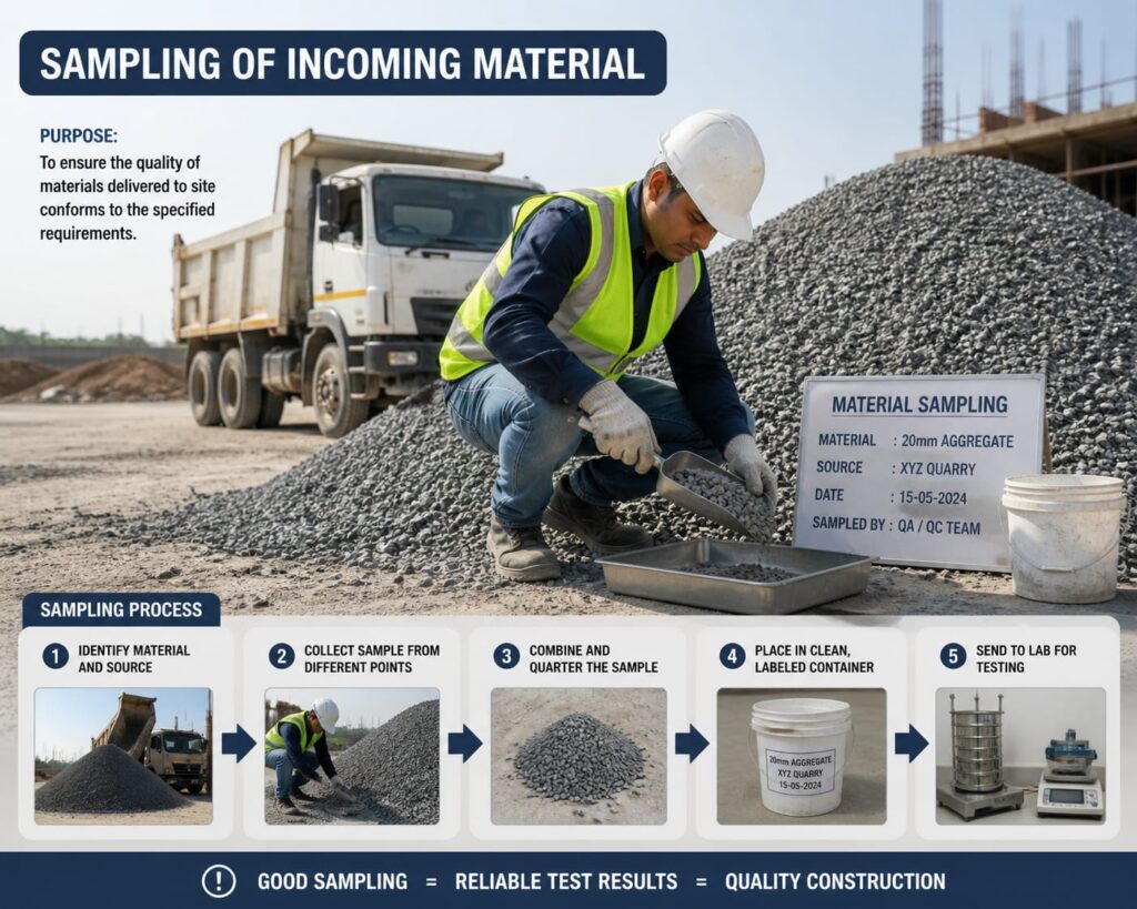
SAMPLING AND TESTING PROCEDURE FOR CEMENT: Check the seal number as per invoice of the browser. If the seal found tight and match with the invoice, then collect a representative sample of 20kg for in-house testing in the presence of client. Conduct the routine test like fineness, % passing on 90 mic sieve and allow for unload, if found complied to IS 4031. The tests like consistency, soundness, compressive strength, initial and final setting of the cement shall be tested as per IS 4031. Prepare formats for above tests and get it signed by client and file the records. Maintain invoice register for cement receipt at plant. Ensure all the tests shall be performed as per week number of the cement. SAMPLING AND TESTING OF REINFORCEMENT: Once the reinforcement lots arrived to site from approved sources, unload the material in stacking yard. Inspect the reinforcement lot as per invoice and ensure tagging of reinforcement for every lot. Collect 2 samples (3 pieces of 1m length for each sample) from every dia of reinforcement for a lot of 50t and 3 samples for 100MT. Bring the cutting pieces to lab and in the sampling register. Check the weight per running meter for the samples collected. Rolling margin of all samples shall be collected for every lot. If the rolling margin found within the tolerable limits as per IS 1786-2008, accept the lot. Otherwise inform to supplier to take back the lot. Invoice with test certificate shall be verified by quality in charge and sign on test certificate. Enter the details of reinforcement received in the invoice register and get the signature of client. If any lot required for independent lab testing, raise RFI and collect the samples in the presence of client. Sign the sample card by client and IE representatives and keep one copy in lab and other copy to tie for sample pieces. Physical and chemical properties of the reinforcement tested in independent lab shall be reviewed by quality in charge and client and ensure complied to IS 1786-2008. The test reports of independent lab will be submitted to client for review and approval. SAMPLING AND TESTING OF FINE AGGREGATE: Once the fine aggregate (river sand) load received at site from approved source, collect a representative sample of 20kg for lab testing to check physical properties. Enter the details of river sand in the sampling register. The material shall be tested for sieve analysis and check for zone of the sand and Fineness Modulus (FM). Check the silt content of the sand as per IS 2386. If the sand falls in zone-II and the FM lies in between 2 to 3.5 and the silt content less than 3% , the vehicle shall be allowed for unloading . If the sand doesn’t meet the above requirements (FM and silt content) shall be rejected. If the sand contains over size material more than 10% on 10mm sieve shall be screened and use for permanent works. Independent lab testing of sand shall be tested as per approved ITP. SAMPLING AND TESTING OF BITUMEN: Once the bitumen tanker arrived at site, verify the invoice number and seal of the tanker. Collect the sample with sampler of weight not less than 1 kg. Enter the sample details in sampling register and sample number shall be given. Test the sample for absolute viscosity, softening point, and penetration. If the test results found satisfactory, allow the tanker for unload. Review the conducted test results and compare with MTC. Prepare the test reports and get it signed by client and file the records. Maintain the invoice register for incoming bitumen and get the signature in theregister by client. The sample shall be collected for independent lab testing frequency as per theapproved ITP. SAMPLING AND TESTING OF ADMIXTURE: Once the admixture barrels arrived at site, verify the invoice number and batch number of the material. Collect the sample with sampler of weight not less than 2 kg. Enter the sample details in sampling register and sample number shall be given. Test the sample for density at room temperature. If the test results found satisfactory, then allow the admixture to use in permanent work. Review the MTC test results as per IS 9103. Maintain the invoice register for incoming bitumen and get the signature in the register by client. SAMPLING AND TESTING OF EMULSION (SS-1 & RS-1): Once the emulsion tanker arrived at site, verify the invoice number and seal of the tanker. Collect the sample with sampler of weight not less than 1 kg. Enter the sample details in sampling register and sample number shall be given. Test the sample for viscosity by say bolt furl viscometer. If the test results found satisfactory, allow the tanker for unload. Conduct the balance tests like residue test by evaporation. Review the conducted test results and compare with MTC. Prepare the test reports and get it signed by client and file the records. Maintain the invoice register for incoming emulsions and get the signature in the register by client. The sample shall be collected for independent lab testing frequency as per the approved ITP. SAMPLING AND TESTING OF GEO-GRIDS / GEO-TEXTILE: Once the Geogrid material arrived at site, verify the invoice number and grade. Raise the RFI and Collect the sample from bundle I roll of size not less than 2m*2m from each grade. Enter the sample details in sampling register and sample number shall be given. Count the number of ribs in machine direction and transverse direction. The samples shall be tagged with sample card mentioned all the details with signatures of client. The collected samples shall be sent for independent lab testing as per approved ITP. Review the MTC test results as per grade requirement. Maintain the invoice register for Geogrid and get the signature of client. TEST PROCEDURE OF CTSB MIX DESIGN Raise RFI for sampling of aggregates for CTSB Mix Design. Sample the individual aggregates jointly. Do individual gradation for each aggregate as mentioned in MoRTH
Borrow Area Method Statement as per MoRTH | QA/QC Construction Procedure
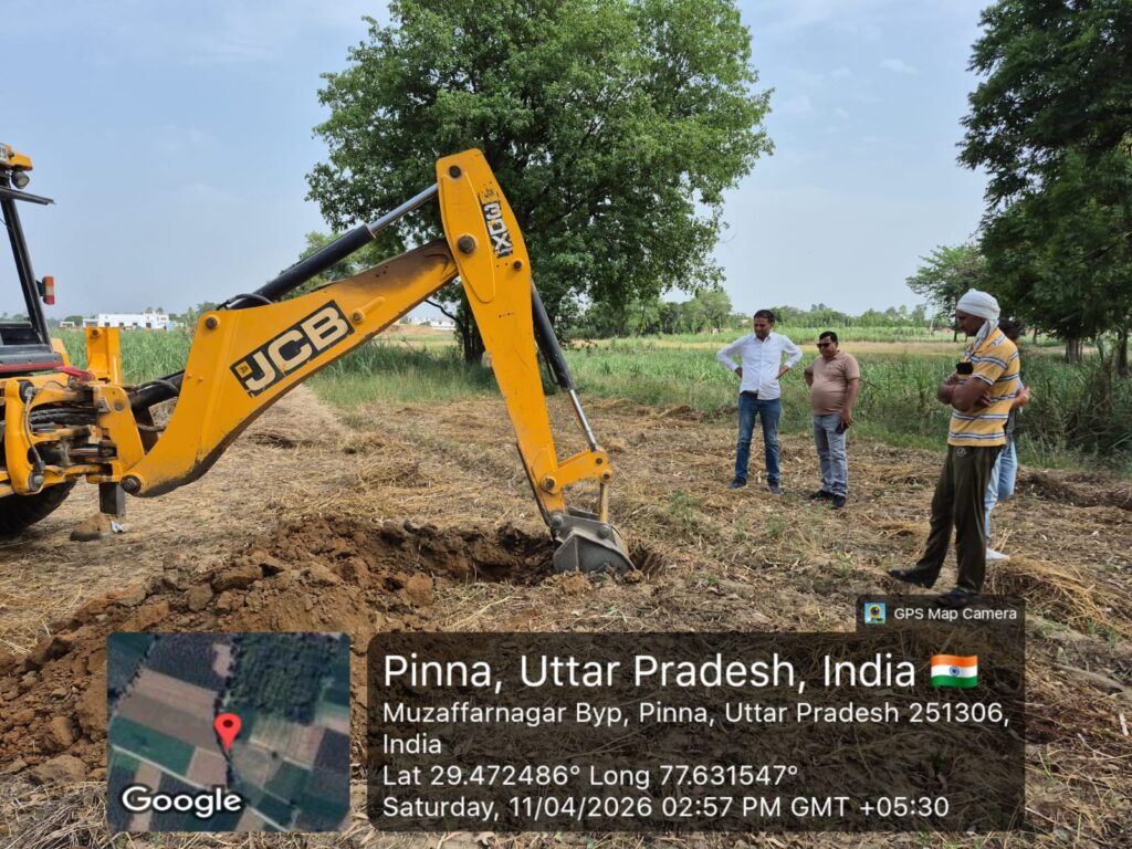
METHOD STATEMENT FOR BORROW AREA Scope This method Statement covers the work involved in obtaining borrow Material for work under this contract, including negotiations with owners of the land on which borrow areas are situated, cleaning the site, stripping and disposing of excess overburden, excavating selected material for use in the work, and finishing –off the borrow areas. Reference MoRT&H Specification clause No 301 to 303 and technical specification of contract Equipment Excavators, Dumpers Negotiations with owners and authorities We shall be responsible for all negotiations with and compensation of owners for all borrow area that we shall identify and prescribe. However, for those that are identified are prescribed by the employer consultants, we shall exempted from all obligations and costs in respect of negotiations with and compensations of the owners of the land on which the borrow area situated. Use of Borrow area Having concluded verbally and in written all the necessary negotiations with the owners of the ground on which any borrow area is situated. We shall open such a borrow area. The notification to the land owners will be at least 7days before prospecting and the engineer will also informed accordingly. Obtaining Borrow area material General The arrangement for the source of supply of the material for embankment and sub grade and compliance with the guidelines, and environmental requirements, in respect of excavation and borrow area as stipulated from time to time by the ministry of Environmental and forests, government of India and the local bodies, as applicable shall be sole responsibility of the contractor Borrow pits along the road shall be discouraged. If permitted by the engineer, these shall not be dug continuously. Ridges of not less than 8m width should be left at intervals not exceeding 300m. Small drains shall be cut through the ridges to facilities drainage. The depth of the pits shall be so regulated that their bottom does not cut an imaginary line having a slope of 1 vertical to 4 horizontal projected from the edge of the final section of the bank, the maximum depth in any case being limited to 1.5 m. also, no pits shall be dug within the offset width of a minimum of 10m Borrow material shall be obtained from approved sources of supply listed and described on the borrow area plans. Or from such other sources as may from time to time be tested and approved by the engineer. Use for Borrow area material The decision as to which source of supply of borrow material shall be used at any time shall rest with the engineer, and we shall at any stage of work use that approved source of supply which in the opinion of the engineer is the most suitable in regard to the quality and quantities of the various types of available materials and the ultimate cost of the work to the employee. Should there be need to obtain material from sources other than those shown on the borrow area schedule, we shall excavate the necessary trail holes, and take such samples and conduct or have conducted such tests as are deemed to be necessary by the engineer, we shall submit the results and sufficient details to the engineer to satisfy him that the quality and quality of the material available in the proposed borrow area are acceptable for the intended use, all at our own expense. Compensation to owners and arrangements for taking any material shall be In terms of the project specification. Approval of borrow area shall apply only to those portions of the area from which acceptable material can be obtained or produced. We shall organelles our operations in any approved borrow area or portions thereof with a view to using the material for the purpose envisaged. We shall plan our exploitation of the borrow area in such a manner that the various types of materials excavated can be selected and loaded directly for use. When this is unfeasible for reasons beyond our control, material to be stockpiled for later use shall be loaded, transported and temporarily stockpiled as ordered by the engineer and as determined in clause 3203 of SATCC specifications. No material reversed for a specific purpose shall be used for any other purpose without the written approval of the engineer. Where suitable sources of materials are available in existing cuttings and side drains, or anywhere else in the road prism or within the road reverse boundaries, such material shall be used for the construction of fills, pavement layers and shoulders, if approved by the engineer. Opening and working on Borrow area and Haul Roads Removing topsoil Prior to opening a borrow area; we shall ascertain from the engineer whether the removal to topsoil is required and shall then remove and stockpile such topsoil as instructed by the engineer. This work shall be carried out, measured and paid for in accordance. Clearing and grubbing Clearing and grubbing of borrow area will be measured of payment in accordance with the provisions before excavation is commenced, but only in the following cases, unless otherwise directed by the engineer (i) In borrow area located in paginations. (ii) In borrow area where large trees with trunk exceeding 1.0 m in circumference (iii) Borrow area without any excess overburden but where the removal of grass shrubs and roots is required. Unless the cleaning and grubbing of a borrow area have been prescribed by the engineer in writing, no payment will be made for cleaning and grubbing such borrow area. Thos applies practically to borrow areas opened for obtaining rock or sand used in the construction of stone-pitching, concrete work, crushed-stone base or sub-base permeable subsurface drain material or surfacing. Excess overburden We shall advise the engineer in good time, before any excavation at such borrow area is commenced, of his intension of staffing to use a borrow area in order that a survey of
Grain Size Analysis (Sieve Analysis) of Soil – Procedure, Calculations & Results
Grain Size Analysis of Soil – Sieve Analysis Procedure, Calculation & Interpretation Author: Kishor Kumar · Updated: February 2026 · Read time: ~15 minutes 1. Introduction The Grain Size Analysis of Soil, commonly known as the Sieve Analysis, is a fundamental laboratory test used to determine the particle size distribution of soil. It plays a crucial role in highway and civil engineering projects. Soil Identification and Classification Most of the methods for soil identification and classification are based on certain physical properties of the soils. The commonly used properties for the classification are the grain size distribution, liquid limit and plasticity index. These properties have also been used in empirical design methods for flexible pavements, and in deciding the suitability of sub grade soils. Grain size analysis also known as mechanical analysis of soils is the determination of the percent of individual grain sizes present in the sample. The mechanical analysis consists of two parts: Determination of coarse material using sieves. Analysis of fine grained fraction by sedimentation method. The sieve analysis is a simple test consisting of sieving a measured quantity of material through successively smaller sieves. The weight retained on each sieve is expressed as a percentage of the total sample. The sedimentation principle has been used for finding the grain size distribution of fine soil fraction; two methods are commonly used: Pipette method Hydrometer method The grain size distribution of soil particles of size greater than 75 micron is determined by sieving the soil on a set of sieves of decreasing sieve opening placed one below the other and separating out the different size ranges. Two methods of sieve analysis are as follows: Wet sieving applicable to all soils Dry sieving applicable only to soils, which have negligible proportion of clay and silt The soil received from the field is divided into two parts: one, the fraction retained on 2mm sieve and the other passing 2mm sieve. The sieve analysis also may be carried out separately for these two fractions. The fraction retained on 2mm sieve may be subjected to dry sieving using bigger sieves and that passing 2mm sieve may be subjected to wet sieving; however if this fraction consists of single grained soil with negligible fines passing 0.075mm size, dry sieving may be carried out. Proper soil gradation ensures good drainage, uniform compaction, and strong load-bearing capacity. Coarse-grained soils are generally suitable for sub-base layers, while fine-grained soils may require stabilization. 2. Purpose of Grain Size Analysis Determine particle size distribution and gradation Assist in soil classification (Gravel, Sand, Silt, Clay) Design subgrade, embankment, and pavement layers Assess permeability and drainage characteristics Guide soil stabilization decisions 3. Applicable Standards IS 2720 (Part 4) – Grain Size Analysis IS 2720 (Part 1) – Sample Preparation MoRTH Specifications – Subgrade, GSB & WMM ASTM D6913 / D422 – International standards 4. Apparatus Required Standard sieve set (4.75 mm to 75 μm) Mechanical sieve shaker Weighing balance (0.1 g accuracy) Oven (105°C to 110°C) Hydrometer (for fine soils) Brush, spatula, containers 5. Sample Preparation The soil sample should be oven-dried at 105°C–110°C and cleaned of organic matter. Lumps should be broken gently without crushing particles. Take ~500 g dry soil sample Ensure moisture content is minimal Remove oversized particles and debris Mix thoroughly for uniformity 6. Test Procedure – Sieve Analysis Sieve Analysis – Coarse Fraction (a) Fraction retained on 2.0mm sieve: Sufficient quantity of the dry soil retained on 2.0mm sieve is weighed out. The quantity of sample taken may be increased when the maximum size of particles is higher. The sample is separated into various fractions by sieving through the set of sieves of sizes 100 mm, 63 mm, 20 mm, 6 mm, 4.75 mm and 2 mm IS sieves. Additional sieve sizes may also be introduced if necessary. After initial sieving, the material retained on each sieve is collected, the lumps are broken down using mortar and rubber covered pestle and is re-sieved. Thus, the soil fraction retained on each sieve is carefully collected and weighed. Sieve Analysis – Fine Fraction (b) For the fraction passing 2.0mm sieve and retained on 0.075mm sieve: Dry sieving may be done in the case of soils which are cohesion less, single grained and without lumps. Rifling or quartering method takes the required quantity of soil sample, dried in oven at 1050 to 1100°C and is subjected to dry sieve analysis using a set of sieves with sieve openings 2.0 mm, 0.6 mm, 0.425 mm, 0.15 mm and 0.075 mm, pan and lid. Additional sieves may be used or any of the sieves removed, depending upon the requirement of the test. The material retained on each sieve and on the pan are separately collected and weighed. Wet sieving may be adopted in the case of clayey or cohesive soils. Required quantity of sample taken by riffling is weighed. The sample is spread in a tray or bucket and covered with water. In case of soils having fractions that are likely to flocculate, a dispersing agent like sodium hexametaphosphate (2.0g) or sodium hydroxide (1.0g) and sodium carbonate (1.0g) per liter of water may be added to the water. The mix is stirred and left for soaking. The soaked soil specimen is placed over the set of sieves with the finest sieve and pan at the bottom and washed thoroughly. Washing is continued till the water passing each sieve is substantially clean. The fraction of each sieve is emptied carefully without loss of material in separate trays, oven dried at 1050 to 1100°C and each fraction weighed separately. Calculations – Sieve Analysis CALCULATIONS: The weight of dry soil fractions retained on each sieve is calculated as a percentage of the total dry weight of the sample taken. Results – Grain Size Analysis RESULTS: The results are plotted on a semi-logarithmic graph with the grain size or sieve size on the X-axis (log scale) and the percentage finer of each sieve on the Y-axis (ordinary scale). The smooth curve joining the
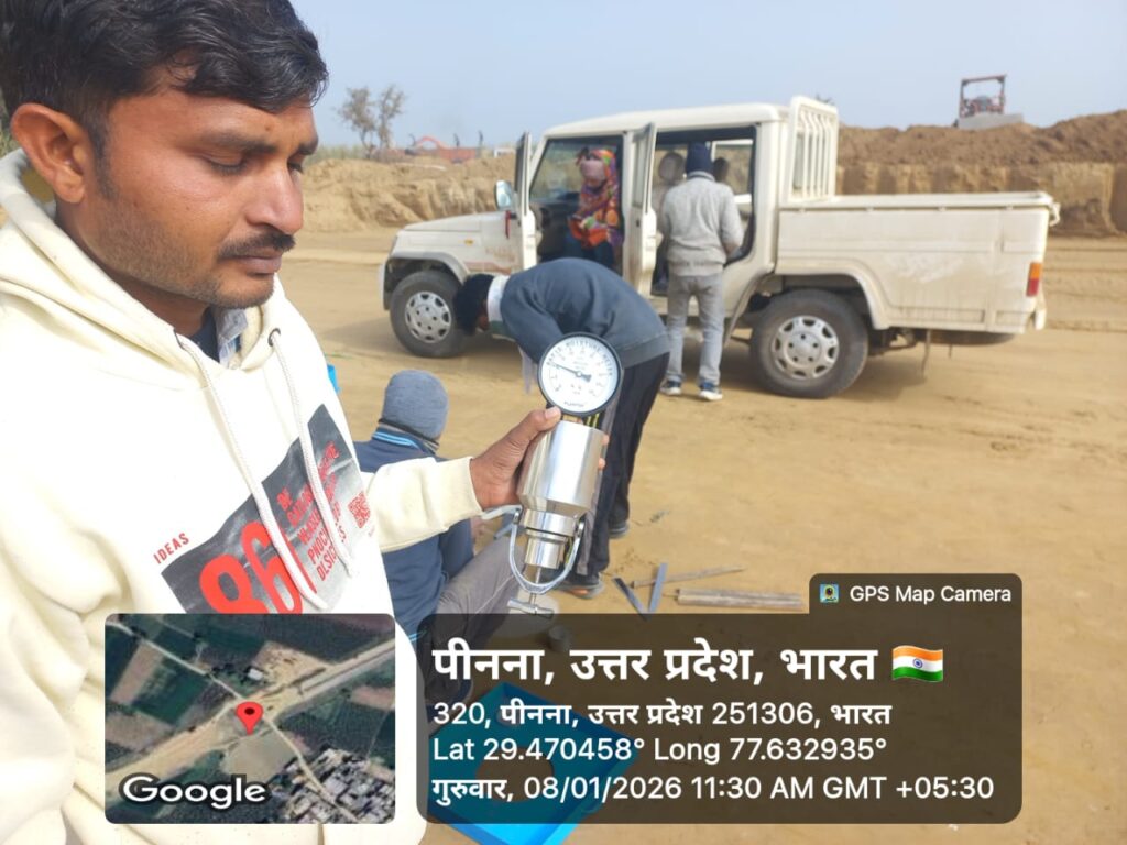
California Bearing Ratio Test
The CBR test evaluates the strength of subgrade soil, sub-base, or base course material under controlled compaction and moisture conditions. The value obtained is used in pavement thickness design.
Moisture Content of Soil Test – Objective, Procedure & Calculation
To determine the Moisture content of SOIL
Liquid Limit of Soil
he Liquid Limit (LL) Test determines the water content at which soil changes from a plastic to a liquid state. It is a key parameter for classifying soils, evaluating their plasticity, and assessing suitability for highway and civil engineering works.
Plastic Limit of Soil

Plastic Limit of Soil Test (PL Test) – Procedure & Calculations Plastic Limit of Soil Test (PL Test) The Plastic Limit of Soil (PL) is defined as the moisture content at which a fine‑grained soil begins to exhibit plastic behavior — it can be deformed without cracking or crumbling. Determining the PL is a key part of soil classification and geotechnical evaluation for engineering works. The outcome of the PL Test is used to compute important indices like Plasticity Index (PI), Liquidity Index (LI), and Consistency Index (CI), which help engineers predict settlement potential, shrink-swell behavior, and workability during construction. This test is part of a suite of soil evaluations. For example, the Liquid Limit of Soil test complements the PL Test by identifying when soil transforms to a liquid state. The Modified Proctor Compaction Test determines optimum moisture content and maximum dry density, and the CBR Test evaluates soil bearing capacity for pavement design. Introduction Fine-grained soils such as silts and clays change behavior depending on water content. These behaviors are categorized under Atterberg limits: Liquid Limit (LL): Water content at which soil behaves like a liquid. Plastic Limit (PL): Water content at which soil exhibits plasticity. Shrinkage Limit (SL): Water content at which further drying does not result in volume change. The Plastic Limit is considered the lower bound of the plastic state. Soils with higher PL tend to be more cohesive and resist deformation. Accurate PL determination is essential for earthwork design, foundation engineering, and soil suitability assessment in pavement and structural applications. Objective of Plastic Limit Test To determine the Plastic Limit (PL) as per IS standards. To classify soils based on plasticity characteristics. To calculate key soil indices like PI, LI, and CI. To assess soil workability, compaction behavior, and moisture sensitivity. Apparatus Required Evaporating dish for collecting crumbled soil. Spatula and mixing tray. Glass plate for rolling soil threads. Moisture containers with lids for storing samples. Rolling rod (3 mm diameter) for thread rolling. Sensitive balance with accuracy of 0.01 g. Oven maintained at 105–110 °C for moisture determination. Sample Preparation Collect soil passing through a 425 μm IS sieve for fine-grained behavior. Air-dry and break down clumps for uniformity. Take 20–25 g of soil for testing. Add distilled water gradually to form a uniform plastic paste. Mix thoroughly and allow brief equilibrium. Procedure for Plastic Limit Test Sl. No. 1: About 20 g of dry pulverized soil passing 425 micron IS sieve is weighed. The soil is mixed thoroughly with distilled water in the evaporating dish till the soil paste is plastic enough to be easily moulded with fingers. Sl. No. 2: A small ball is formed with the fingers and this is rolled between the fingers and glass plate to a thread. The pressure just sufficient to roll into a thread of uniform diameter should be used. Sl. No. 3: The rate of rolling should be between 80 to 90 strokes per minute, counting a stroke as one complete motion of hand forward and back to the starting position again. Sl. No. 4: The rolling is done till the diameter of the thread is 3 mm. Then the soil is kneaded together to a ball and rolled again to form thread. Sl. No. 5: This process of alternate rolling and kneading is continued until the thread crumbles under pressure required for rolling and the soil can no longer be rolled into a thread. Sl. No. 6: If the crumbling starts at diameter less than 3 mm, then moisture content is more than plastic limit and if the diameter is greater while crumbling starts, the moisture content is lower. Sl. No. 7: By trial, the thread that starts crumbling at 3 mm diameter under normal rolling should be obtained and this should be immediately transferred to the moisture container, lid placed over it and weighed. Sl. No. 8: The container is kept in the oven for about a day and dry weight found to determine the moisture content of the thread. Sl. No. 9: The above process is repeated to get at least three consistent values of the plastic limit (PL or WP). Calculations Plasticity Index (PI) PI = Liquid Limit (LL) – Plastic Limit (PL) PI = WL – WP Liquidity Index (LI) LI = (W – WP) / PI Where W = natural moisture content Consistency Index (CI) CI = (WP – W) / PI Toughness Index (TI) TI = PI / IF Where IF = Flow index from Liquid Limit Test Factors Affecting Plastic Limit Soil mineralogy (montmorillonite, kaolinite, etc.) Organic content — higher retention increases PL Sample preparation — inconsistent moisture affects results Rolling technique — uniform pressure improves accuracy Engineering Applications Soil Classification: PL is key for Atterberg limit-based classification. Pavement Subgrades: PL helps identify moisture-sensitive soils. Compaction Control: Guides optimum moisture for target densities. Foundation Behavior: Indicates compressibility and shrink-swell potential. Acceptance Criteria for Construction Soil Type Plastic Limit (PL %) Plasticity Index (PI) Suitability Granular Subgrade > 15 < 10 Suitable Clayey Subgrade 15–25 10–30 Conditional Highly Plastic Clay > 25 > 30 Unsuitable Precautions and Tips Use freshly prepared soil paste. Maintain uniform rolling pressure and speed. Determine moisture immediately after crumbling. Conduct multiple trials for accurate results. Conclusion The Plastic Limit of Soil is an essential measure of plastic behavior in fine-grained soils. Combined with Liquid Limit, Modified Proctor Compaction, and CBR Test, engineers can fully evaluate soil performance for highways, foundations, and earthworks. Accurate PL determination ensures better design, compaction control, and soil suitability assessment. ([highwayqualitytest.com](https://highwayqualitytest.com/modified-proctor-test/?utm_source=chatgpt.com)) 🔬 Related Highway & Pavement Tests Explore detailed test procedures, calculations and acceptance criteria as per IS, MoRTH & IRC specifications: ✅ CBR Test – Subgrade Strength ✅ Field Density Test (Core Cutter) ✅ Plasticity Index Test ✅ Free Swell Index Test 🪨 Aggregate Tests: ✅ Aggregate Impact Value Test ✅ Los Angeles Abrasion Test ✅ Aggregate Crushing Value Test ✅ Aggregate Water Absorption Test 🛢️ Bitumen Tests: ✅ Marshall Stability & Flow Test 🏗️ Cement
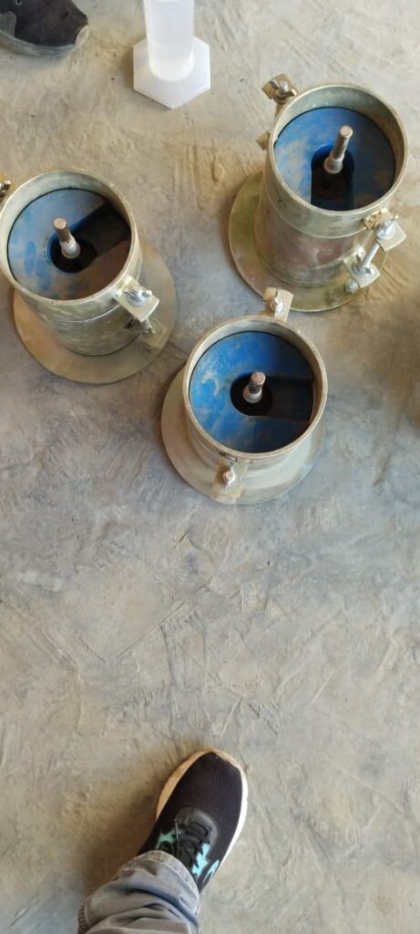
Modified Proctor Compaction Test – Procedure, Calculation & Graph
It helps in understanding how much water should be added to the soil for achieving maximum compaction under a given compactive effort.
Free Swell Index (FSI) Test – Procedure, Formula & Acceptance Criteria (IS 2720 Part 40)
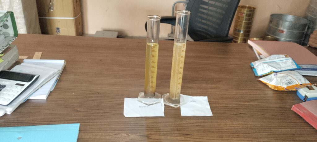
Explore all Soil Tests: Soil Testing Hub Home » Geotechnical Tests » Free Swell Index (FSI) Test Free Swell Index (FSI) Test – Procedure, Formula & Acceptance Criteria (IS 2720 Part 40) Test Standard: IS:2720 (Part 40) | Applicable Codes: MoRTH, IRC:75 (2015), IRC:SP:89 What is Free Swell Index (FSI) Test? The Free Swell Index (FSI) test is a laboratory test used to determine the swelling potential of soil when immersed in water under unconstrained conditions. It helps in identifying expansive soils containing clay minerals such as montmorillonite. Why it matters: High Free Swell Index values may lead to pavement heaving, cracking, and loss of subgrade stability if the soil is used without treatment. Scope & Applicable Standards IS:2720 (Part 40) – Determination of Free Swell Index of Soil MoRTH Section 300 – Subgrade and Earthwork IRC:75 (2015) – Guidelines for Embankments and Subgrades IRC:SP:89 – Soil Testing in Road Works NHAI QA/QC Manual Apparatus Required for FSI Test 425 micron IS sieve Two 100 ml graduated glass cylinders (IS:878) Oven maintained at 110 ± 5 °C Electronic balance with 0.01 g accuracy Distilled water and kerosene Glass rod, spatula and weighing dishes Free Swell Index Test Procedure (IS 2720 Part 40) Take about 500 g of air-dried soil and sieve it through a 425-micron sieve. Weigh two soil samples of 10 g each. Place one sample in each 100 ml graduated cylinder. Fill one cylinder with kerosene and the other with distilled water up to the 100 ml mark. Stir gently to remove entrapped air bubbles. Allow the samples to stand undisturbed for 24 hours at 27 ± 2 °C. Record the final soil volumes: Vk = Volume of soil in kerosene Vw = Volume of soil in water Free Swell Index Formula FSI (%) = [(Vw – Vk) / Vk] × 100 FSI Interpretation and Acceptance Criteria Free Swell Index (%) Swelling Nature Suitability for Subgrade 0 – 20 Low Suitable for direct use 20 – 50 Moderate Use with control measures Above 50 High to Very High Stabilization or replacement required Note: Free Swell Index is an index test and should be used along with Atterberg limits and swell pressure tests for design decisions. Precautions During FSI Test Ensure glass cylinders are clean and dry. Maintain the specified test temperature. Do not disturb the samples during the standing period. Record volume readings accurately. Frequently Asked Questions Is Free Swell Index the same as swell pressure? No. Free Swell Index measures volume increase without restraint, whereas swell pressure measures pressure developed under confinement. Can Free Swell Index alone be used for soil design? No. It is only an indicator test and must be supported by other geotechnical tests. How can expansive soil be treated? Common methods include lime stabilization, cement stabilization, blending with non-expansive soil, or soil replacement. References: IS:2720 (Part 40), MoRTH Specifications, IRC:75 (2015), IRC:SP:89 © 2025 Highway Quality Test
Soil Testing
Soil Testing for Highway Construction | MoRTH & IS Standards – Complete Guide Soil Testing for Highway Construction – Complete Quality Control Guide Soil testing forms the backbone of highway construction quality control. The strength, compaction, and durability of soils directly affect pavement performance, embankment stability, and long-term maintenance costs. Without proper soil testing, highways are prone to settlement, rutting, cracking, and premature failure. This comprehensive guide covers all soil tests required in highway projects as per MoRTH (5th Revision) and IS 2720. Each test includes purpose, procedure, acceptance criteria, and field relevance, with frequency guidelines as per MoRTH Clause 900. 1. Importance of Soil Testing in Highway Construction Highway pavements transmit heavy traffic loads to the underlying soil layers. If the soil lacks adequate strength, compaction, or moisture control, structural distresses appear early, increasing maintenance costs. Ensures construction meets design assumptions Controls moisture and compaction during placement Verifies suitability of borrow materials Supports quality assurance and payment certification Reduces risk of pavement failure and expensive repairs 2. Applicable Standards & References MoRTH Specifications (5th Revision) IS 2720 – Methods of Test for Soils (Parts 1–40) IRC:37 – Guidelines for Embankment & Subgrade IRC:SP:84 – Soil Quality Control Practices Project Technical Specifications 3. Classification of Soil Tests in Highway Works A. Field Tests Field Density Test (Sand Replacement / Core Cutter) In-situ Moisture Content Visual Inspection & Classification of Borrow Material B. Laboratory Tests Grain Size Analysis Atterberg Limits Proctor Compaction Test (Modified / Standard) California Bearing Ratio (CBR) Test Free Swell Index Moisture Content Verification 4. Mandatory Soil Tests & Their Purpose Test Purpose MoRTH Reference Field Density Test Verify achieved compaction on site Clause 903, 305 Modified Proctor Test Determine MDD & OMC IS 2720 (Part 8) CBR Test Assess load-bearing capacity Clause 305, 903 Atterberg Limits Evaluate plasticity & volume change IS 2720 (Part 5) Grain Size Analysis Soil gradation & classification IS 2720 (Part 4) Free Swell Index Check expansive soil behavior IS 2720 (Part 40) Moisture Content Verify optimum moisture for compaction IS 2720 (Part 2) 5. Acceptance Criteria (Key Requirements) Parameter Requirement Field Density – Embankment ≥ 95% of MDD Field Density – Subgrade ≥ 97% of MDD Moisture Content OMC ± 2% CBR (Subgrade) As per design (typically ≥ 8%) Free Swell Index ≤ 50% Atterberg Limits Plasticity Index within project limits 6. Field Quality Control Procedures Quality control is continuous. Before placing any layer, soil moisture is adjusted to OMC. Compaction is done using approved rollers, followed by immediate density verification. Scarify or remix soil if density is below required Adjust moisture content Re-compact and retest Maintain records for all layers 7. Inspection Checklist for Site Engineers ✔ Borrow soil approved by Engineer ✔ Laboratory test reports available ✔ Moisture within OMC range ✔ Layer thickness controlled ✔ Field density test passed ✔ Failed areas rectified and retested ✔ Documentation per MoRTH Clause 903 maintained 8. Detailed Soil Test Procedures by Construction Stage This section organizes soil tests based on construction stage: Original Ground Level (OGL), Embankment, and Subgrade. Each test includes What, Why, and When (MoRTH Clause 900 frequency). 8.1 Original Ground Level (OGL / Borrow Soil) OGL represents the natural ground or borrow material used in embankment construction. Tests here ensure the foundation soil is suitable. Field Density Test – Sand Replacement / Core Cutter What: Measure in-situ density of OGL soil. Why: Ensures soil compaction at natural state meets design assumptions. When: 1 test per 3000 m³ (MoRTH Clause 900). Learn more Grain Size Analysis What: Determine soil particle distribution. Why: Classifies soil for suitability and stability. When: 1 test per 5000 m³ (MoRTH Clause 900). Learn more Atterberg Limits Test What: Determine plasticity and shrink-swell potential. Why: Identifies highly plastic soils that may cause settlement. When: 1 test per 5000 m³ (MoRTH Clause 900). Learn more Free Swell Index Test – Coming Soon Moisture Content Test – Coming Soon Modified Proctor Compaction Test – Coming Soon 8.2 Embankment Layer The embankment is the built-up layer above OGL. Tests ensure proper compaction, layer thickness, and material quality for load-bearing. Field Density Test What: Measure compaction of each embankment layer. Why: Prevents settlement and ensures design strength. When: 1 test per 250 m³ per layer (MoRTH Clause 900). Coming Soon Moisture Content Test What: Ensure soil is at Optimum Moisture Content before compaction. Why: Moisture outside OMC reduces compaction efficiency. When: 1 test per 250 m³ per layer (MoRTH Clause 900). Coming Soon Modified Proctor Compaction Test What: Determine MDD and OMC for embankment soil. Why: Guides compaction process for each layer. When: 1 test per soil type or 10000 m³ (MoRTH Clause 900). Coming Soon CBR Test What: Assess load-bearing capacity of embankment layer. Why: Ensures embankment can support pavement layers. When: 1 test per 5000 m³ (MoRTH Clause 900). Learn more 8.3 Subgrade Layer Subgrade is the topmost soil layer that directly supports the pavement. Quality here is critical for long-term pavement performance. Field Density Test What: Measure density after final compaction of subgrade. Why: Prevents differential settlement and ensures uniform support. When: 1 test per 200 m² (MoRTH Clause 900). Coming Soon Moisture Content Test What: Verify soil moisture is within ±2% of OMC. Why: Ensures optimal compaction for design strength. When: 1 test per 200 m² (MoRTH Clause 900). Coming Soon CBR Test What: Evaluate subgrade strength and pavement design adequacy. Why: Determines structural capacity for traffic loads. When: 1 test per 500 m² (MoRTH Clause 900). Learn more Atterberg Limits / Plasticity Check What: Detect highly plastic soils in subgrade. Why: High plasticity soils may cause swelling, shrinkage, and cracking. When: 1 test per 5000 m³ (MoRTH Clause 900). Coming Soon Free Swell Index What: Measure potential for soil expansion. Why: Prevents distress in subgrade and pavement. When: 1 test per 5000 m³ (MoRTH Clause 900). Learn more 9. Common Site Issues & Rectification Low density → Increase roller passes or adjust moisture content High plasticity → Blend with granular material or use chemical