
Methodology for Pre-stressing of HTS Strands
Methodology for Pre-stressing of HTS Strands This item of work deals with the activity of Pre-stressing of H.T.S strands of PSC girders with approved materials as per the specifications of the Contract Agreement. General This item of work shall be carried out in compliance with Clause 1800 of MoRTH Specifications. The materials shall conform to Section 1000 and the grout mix shall conform to Section 1808 of MoRTH Specifications. Procedure 1. Cable Fabrication & Laying The length of cable required shall be computed from the drawing including allowances for profiling and gripping length of jack. The strand shall be cut evenly using an abrasive cutter to the required length. Both ends of the cable shall be numbered to maintain correct configuration in the bearing plate and prevent twisting in the duct. The duct shall be profiled as per approved ordinates and cable shall be threaded manually into the duct. Grout vents shall be provided wherever required. Tube ducts of the anchorage shall be fixed with end blocks as shown in drawings. The ducts shall be connected to tube units. The cable consisting of the specified number of strands shall be tied with binding wire at regular intervals and threaded into sheathing. Both ends of the duct shall be closed after strand installation and protruding strands shall be wrapped properly to avoid dirt entry during concreting. 2. Concreting During concreting, cables shall be moved manually at suitable intervals to avoid concrete blockage inside ducts. The strands beyond the bearing plate shall be cleaned using petrol after concreting to remove dust and rust. 3. Stressing Operation Stressing of cables may be carried out from both ends. Bearing plates shall be cleaned and fixed in proper configuration. Wedges shall be fixed to bearing plates and tightened. Jacks shall be mounted properly and aligned with the cable. Master grips of the jack shall be inserted over strands and fixed into pulling plates. Stressing pumps shall be connected to jacks through hose pipes. Correction factor shall be calculated from pressure and elongation readings. Initial pressure of 50 kg/cm² shall be applied to remove cable slackness. Pressure shall then be increased gradually and elongation readings recorded. Tensioning force shall be verified by pressure gauge readings and elongation comparison. Acceptance Criteria During Stressing If calculated elongation is achieved before specified pressure, stressing shall continue till specified pressure is reached provided elongation does not exceed 1.05 times calculated elongation. If specified pressure is reached before calculated elongation, stressing may continue in intervals of 5 kg/cm² provided pressure does not exceed 1.05 times specified pressure. If elongation remains less than 0.95 times calculated elongation at 1.05 times specified pressure: Check functioning of jack, pump and hose pipes. Detension the cable and check for duct blockage. On achieving full load, wedges shall be locked hydraulically. Jack shall be released and retracted. The same procedure shall be repeated for all cables. 4. Grouting All protruding ends of strands shall be cut after prestressing. Nozzles and valves shall be fitted to grout holes. Ducts shall be flushed with lime water before grouting. Grout shall be prepared using Ordinary Portland Cement and non-shrink grout admixture. Grouting shall commence with low pressure until grout flows out from the other end. The outlet shall be closed once grout consistency becomes uniform. After achieving desired pressure, inlet valve shall be closed. Equipment / Machinery Hydraulic Jack Pressure Gauge Compressor Grouting Equipment Grout Cube Moulds Tolerances Parameter Permissible Tolerance Variation from specified horizontal profile ±5 mm Variation from specified vertical profile ±5 mm Variation from specified position in member ±5 mm “`
Methodology for Structural Concrete for Bridges and Culverts
Methodology for Structural Concrete for Bridges and Culverts 1. Scope The work shall consist of producing and placing concrete of grade M15 and higher by weigh batching in accordance with MoRTH Specifications, IRC:112, approved drawings, and contract specifications. 2. Reference Contract Agreement IRC: SP: 84-2014 MoRTH Specifications (5th Revision) IRC: 112 Relevant Drawings 3. Setting Out After completion of site preparation, alignment of the structure shall be marked on the ground using lime and string. Structural points such as abutment walls and wing walls shall be pegged accurately. Temporary Bench Marks (TBM) shall be established nearby for level reference and protected throughout construction activities. 4. Materials 4.1 Cement Cement conforming to IS:269 shall be used after ensuring the required design strength. Manufacturer Test Certificates (MTC) shall be submitted to the AE for every consignment. Independent testing shall also be conducted at approved laboratories. 4.2 Coarse Aggregate Coarse aggregates shall be obtained from approved quarries and shall consist of clean, hard, durable crushed stone conforming to Table 1700-7 of MoRTH Specifications / IS 383. 4.3 Fine Aggregate Fine aggregates shall be clean, durable, and free from deleterious materials. Gradation shall conform to Table 1000-2 of MoRTH Specifications / IS 383. 4.4 Water Water used for mixing and curing shall conform to IS 456 and Section 1010 of MoRTH Specifications. Water shall be free from harmful substances. Use of seawater shall not be permitted. 4.5 Reinforcement Steel Reinforcement steel shall conform to Section 1009.3 of MoRTH Specifications and IS 1786. TMT Fe-500 grade bars shall be used as per approved drawings. 4.6 Bending of Reinforcement Bar Bending Schedule (BBS) shall be prepared and submitted for approval before commencement of work. It shall include shape, number, cutting length, and weight of bars including auxiliary reinforcement. All materials shall be approved by the AE before use in construction. 5. Placing of Reinforcement Reinforcement shall be placed as per approved drawings and inspected by the AE before concreting. Bars shall be tied using 1 mm binding wire. Cover blocks of the same concrete grade shall be used. Spacer bars and chairs shall be provided to maintain spacing and cover. Horizontal reinforcement shall be adequately supported to avoid sagging. 6. Proportioning of Concrete Concrete shall be produced using approved design mix by weigh batching. Measuring equipment shall be maintained in proper condition and calibrated periodically. Water-cement ratio shall be maintained considering moisture content of aggregates and weather conditions. 7. Trial Mixes Trial mixes for all grades of concrete shall be carried out at the site laboratory before commencement of work using approved materials. Additional trial mixes shall be conducted whenever there is a change in source or proportion of materials. 8. Equipment Batching Plant Transit Mixer Concrete Pump Vibrators & Vibrator Needles Wheel Loader Excavator Shuttering Material Bar Bending & Cutting Machine 9. Transporting, Placing & Compaction of Concrete Concrete shall be transported using transit mixers or concrete pumps. The delivery pipeline shall have minimum bends. Concrete temperature during placing shall be between 5°C and 40°C. Concrete shall be compacted within 30 minutes of discharge. Concrete shall be placed in layers not exceeding 300 mm compacted thickness. Fresh concrete shall not be placed against concrete older than 30 minutes without proper construction joints. Concreting shall not be carried out when ambient temperature exceeds 40°C. 10. Formwork Formwork shall conform to Section 1500 of MoRTH Specifications and IRC:87. Only steel formwork shall be used. Formwork shall be rigid and true to shape. Damaged formwork shall not be used without repair. Steel tubes used as supports shall have minimum 4 mm wall thickness. 11. Construction Joints Construction joints shall be kept to a minimum and provided as per drawings. Laitance shall be removed and the concrete surface roughened before placing fresh concrete. 12. Curing Water curing shall be carried out using approved water conforming to MoRTH Specifications. Concrete surfaces shall be kept continuously wet. Wet hessian cloth, sacks, or canvas may be used. Curing shall continue for at least 14 days after concreting. 13. Finishing Finishing shall be carried out as per Clause 1713 of Section 1700 of MoRTH Specifications to achieve smooth and durable concrete surfaces.
Soil Testing
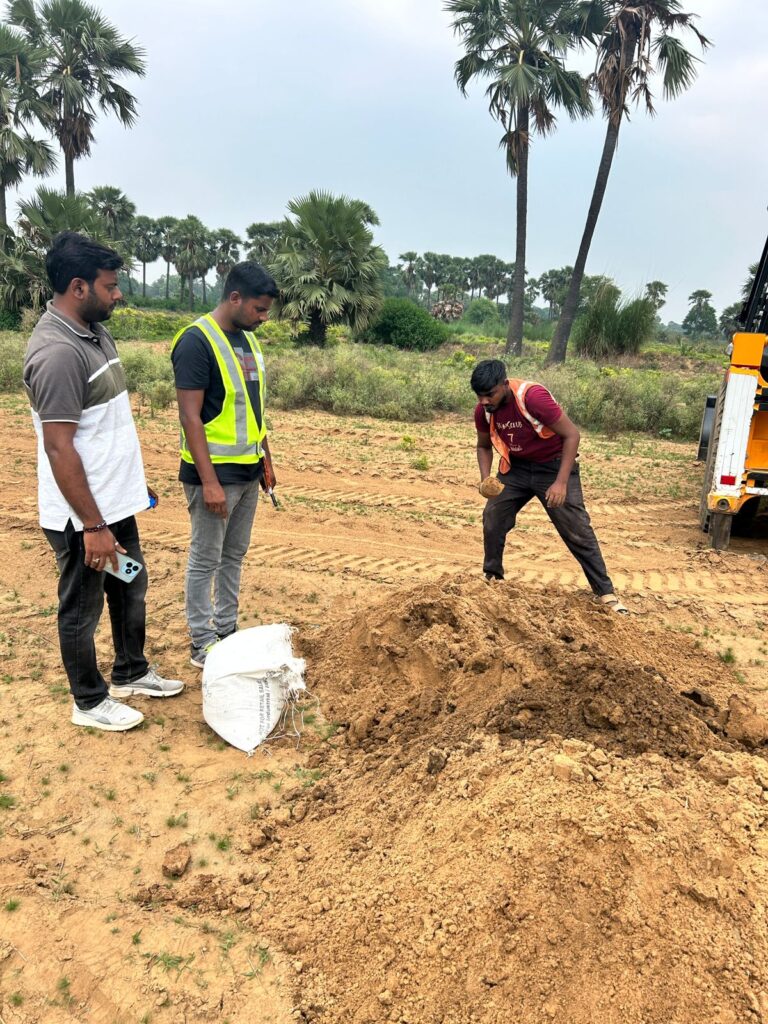
Soil Testing for Highway Construction | MoRTH & IS Standards – Complete Guide Soil Testing for Highway Construction – Complete Quality Control Guide Soil testing forms the backbone of highway construction quality control. The strength, compaction, and durability of soils directly affect pavement performance, embankment stability, and long-term maintenance costs. Without proper soil testing, highways are prone to settlement, rutting, cracking, and premature failure. This comprehensive guide covers all soil tests required in highway projects as per MoRTH (5th Revision) and IS 2720. Each test includes purpose, procedure, acceptance criteria, and field relevance, with frequency guidelines as per MoRTH Clause 900. 1. Importance of Soil Testing in Highway Construction Highway pavements transmit heavy traffic loads to the underlying soil layers. If the soil lacks adequate strength, compaction, or moisture control, structural distresses appear early, increasing maintenance costs. Ensures construction meets design assumptions Controls moisture and compaction during placement Verifies suitability of borrow materials Supports quality assurance and payment certification Reduces risk of pavement failure and expensive repairs 2. Applicable Standards & References MoRTH Specifications (5th Revision) IS 2720 – Methods of Test for Soils (Parts 1–40) IRC:37 – Guidelines for Embankment & Subgrade IRC:SP:84 – Soil Quality Control Practices Project Technical Specifications 3. Classification of Soil Tests in Highway Works A. Field Tests Field Density Test (Sand Replacement / Core Cutter) In-situ Moisture Content Visual Inspection & Classification of Borrow Material B. Laboratory Tests Grain Size Analysis Atterberg Limits Proctor Compaction Test (Modified / Standard) California Bearing Ratio (CBR) Test Free Swell Index Moisture Content Verification 4. Mandatory Soil Tests & Their Purpose Test Purpose MoRTH Reference Field Density Test Verify achieved compaction on site Clause 903, 305 Modified Proctor Test Determine MDD & OMC IS 2720 (Part 8) CBR Test Assess load-bearing capacity Clause 305, 903 Atterberg Limits Evaluate plasticity & volume change IS 2720 (Part 5) Grain Size Analysis Soil gradation & classification IS 2720 (Part 4) Free Swell Index Check expansive soil behavior IS 2720 (Part 40) Moisture Content Verify optimum moisture for compaction IS 2720 (Part 2) 5. Acceptance Criteria (Key Requirements) Parameter Requirement Field Density – Embankment ≥ 95% of MDD Field Density – Subgrade ≥ 97% of MDD Moisture Content OMC ± 2% CBR (Subgrade) As per design (typically ≥ 8%) Free Swell Index ≤ 50% Atterberg Limits Plasticity Index within project limits 6. Field Quality Control Procedures Quality control is continuous. Before placing any layer, soil moisture is adjusted to OMC. Compaction is done using approved rollers, followed by immediate density verification. Scarify or remix soil if density is below required Adjust moisture content Re-compact and retest Maintain records for all layers 7. Inspection Checklist for Site Engineers ✔ Borrow soil approved by Engineer ✔ Laboratory test reports available ✔ Moisture within OMC range ✔ Layer thickness controlled ✔ Field density test passed ✔ Failed areas rectified and retested ✔ Documentation per MoRTH Clause 903 maintained 8. Detailed Soil Test Procedures by Construction Stage This section organizes soil tests based on construction stage: Original Ground Level (OGL), Embankment, and Subgrade. Each test includes What, Why, and When (MoRTH Clause 900 frequency). 8.1 Original Ground Level (OGL / Borrow Soil) OGL represents the natural ground or borrow material used in embankment construction. Tests here ensure the foundation soil is suitable. Field Density Test – Sand Replacement / Core Cutter What: Measure in-situ density of OGL soil. Why: Ensures soil compaction at natural state meets design assumptions. When: 1 test per 3000 m³ (MoRTH Clause 900). Learn more Grain Size Analysis What: Determine soil particle distribution. Why: Classifies soil for suitability and stability. When: 1 test per 5000 m³ (MoRTH Clause 900). Learn more Atterberg Limits Test What: Determine plasticity and shrink-swell potential. Why: Identifies highly plastic soils that may cause settlement. When: 1 test per 5000 m³ (MoRTH Clause 900). Learn more Free Swell Index Test – Coming Soon Moisture Content Test – Coming Soon Modified Proctor Compaction Test – Coming Soon 8.2 Embankment Layer The embankment is the built-up layer above OGL. Tests ensure proper compaction, layer thickness, and material quality for load-bearing. Field Density Test What: Measure compaction of each embankment layer. Why: Prevents settlement and ensures design strength. When: 1 test per 250 m³ per layer (MoRTH Clause 900). Coming Soon Moisture Content Test What: Ensure soil is at Optimum Moisture Content before compaction. Why: Moisture outside OMC reduces compaction efficiency. When: 1 test per 250 m³ per layer (MoRTH Clause 900). Coming Soon Modified Proctor Compaction Test What: Determine MDD and OMC for embankment soil. Why: Guides compaction process for each layer. When: 1 test per soil type or 10000 m³ (MoRTH Clause 900). Coming Soon CBR Test What: Assess load-bearing capacity of embankment layer. Why: Ensures embankment can support pavement layers. When: 1 test per 5000 m³ (MoRTH Clause 900). Learn more 8.3 Subgrade Layer Subgrade is the topmost soil layer that directly supports the pavement. Quality here is critical for long-term pavement performance. Field Density Test What: Measure density after final compaction of subgrade. Why: Prevents differential settlement and ensures uniform support. When: 1 test per 200 m² (MoRTH Clause 900). Coming Soon Moisture Content Test What: Verify soil moisture is within ±2% of OMC. Why: Ensures optimal compaction for design strength. When: 1 test per 200 m² (MoRTH Clause 900). Coming Soon CBR Test What: Evaluate subgrade strength and pavement design adequacy. Why: Determines structural capacity for traffic loads. When: 1 test per 500 m² (MoRTH Clause 900). Learn more Atterberg Limits / Plasticity Check What: Detect highly plastic soils in subgrade. Why: High plasticity soils may cause swelling, shrinkage, and cracking. When: 1 test per 5000 m³ (MoRTH Clause 900). Coming Soon Free Swell Index What: Measure potential for soil expansion. Why: Prevents distress in subgrade and pavement. When: 1 test per 5000 m³ (MoRTH Clause 900). Learn more 9. Common Site Issues & Rectification Low density → Increase roller passes or adjust moisture content High plasticity → Blend with granular material or use chemical