HIGHWAY QUALITY TEST

Precision Testing. Proven Quality. Safer Infrastructure.

Kishor Kumar

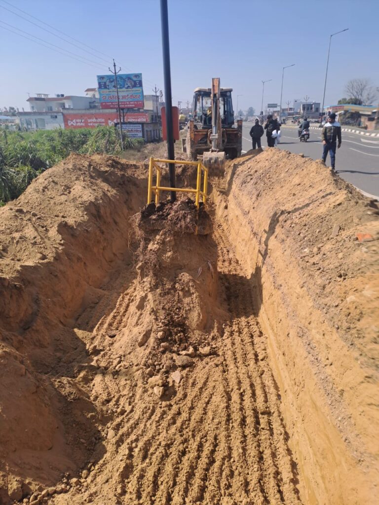
METHOD STATEMENT FOR ROADWAY EXCAVATION

Scope of Work – Excavation Scope  This work shall consist of excavation by mechanical means in all types of soil in final line, level, grades, cross section as shown in drawings for roadways drains, shoulders, median and foundation for structures, including hauling suitable excavation materials to site for embankment and sub grade construction also disposal of unsuitable cut materials specified manner. Reference  MoRT&H Specification clause No 301 to 303 and technical specification of contract Equipment  Excavators, Dumpers, dewatering arrangements Tools  Line rope, lime powder, pegs etc. Manpower & Responsibilities  Construction manager, Earth work engineer/supervisor, land surveyor, material engineer, safety supervisor, helpers Construction Manager He shall be overall responsible for the activity including planning, organising the resources required to carry out the work in consultation with the project manager, implement and ensure safety requirements during the work including that of utility services. Ensures relevant test conducted and records are maintained as per the contract requirements. Coordinate with the consultant engineer in obtaining necessary approvals for the completed activity. Earthwork Engineer / Supervisor Deploying necessary resources at site as planned. Execute the work as per drawing and maintain quality requirements as per specification. Implement and maintain safety regulations and good housekeeping. Coordinate with the consultant staff in obtaining necessary approvals for the completed activity. Land Surveyor Establishing necessary reference points to carry out the work as per the level and alignment. Checking and recording the levels as completed. Coordinate with the consultant staff in obtaining approvals for the finished work. Material Engineer Implement quality procedures as per plan. Ensure the materials used are meeting the specification requirement conduct the required tests as per the relevant specification and maintain all records. Safety Supervisor Ensure that activity is being carried out safely as prescribed in the project safety plan. Procedure General  The excavation shall be set out true to lines curves, grades and sections in works involving removal of existing carriage way, earthen shoulder, median, shall be excavated to the full width and to the required levels, after satisfying CBR and density requirements, as shown in drawings. After reaching to the required depth, it shall be compacted at OMC to achieve min. of 95% for embankment and 97% of MDD for sub grade.  Excavated soil shall be tested for its suitability for reuse or disposal.  The cut formation, which serves as sub grade, if found suitable, shall be loosened, graded, watered and compacted in layers in the specified manner. Any unsuitable material encountered at the sub grade level shall be removed and replaced with suitable material.  While executing excavation all adequate precautions shall be taken to prevent soil erosion and appropriate drainage measures shall be adopted to keep the site free of water stagnation.  The suitable material obtained from excavation shall be used for filling of roadway embankment, sub grade filling of existing pits in the ROW, landscaping etc. All other unsuitable materials shall be disposed of. Surplus suitable material if any shall be stacked at approved locations. Site Clearance  Controlled blasting shall be carried out in fixed hours as ordered by the Engineer and kept known to the public and authorities in the vicinity sufficiently in advance.  Red flags shall be displayed in all directions during blasting operations. People except those who actually light the fuse shall be prohibited from the area and all persons including workmen shall be evacuated from the flagged area at least 10 minutes before firing. A warning alarm or siren shall be sounded for this purpose. The man in-charge shall satisfy himself that all charges are exploded before allowing any workman or people to enter. Firing  The firing of charge holes shall be done by electric detonators by using a sufficiently long fuse wire (at least 10 m) and all charge holes shall be blasted at one instance. Explosive  The explosives for blasting shall be as per permitted explosives as per procedure and requirement. The weight of charge depends upon the quantity of rock to be blasted/excavated, hardness of rock and site condition. Stemming  Stemming may be used if required, of free dry-running material, which passes through 2.8 mm sieve and retained on 1.2 mm sieve by 90%. Muffling  This shall be done to control the fly rock. Since the drill holes are loaded with less charge, sand/earth bags weighing at least 50 kg shall be kept on each charge hole to control fly rock. Safety Measures  All safety measures shall be as per approved EHS Plan.

METHOD STATEMENT FOR ROADWAY EXCAVATION Read More »

Earthwork
METHOD STATEMENT FOR OPEN FOUNDATION

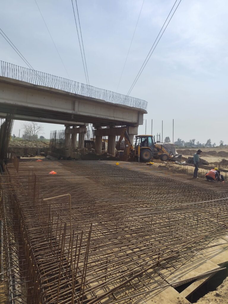
Method Statement for Open Foundation 1. Description This Method Statement covers the construction of Plain Cement Concrete (PCC) and Reinforced Cement Concrete (RCC) Open Foundations in accordance with the approved drawings, contract specifications, and the MoRTH Specifications for Road and Bridge Works. The scope of work includes survey and setting out, excavation, preparation of the foundation bed, dewatering (where required), laying of PCC, reinforcement fixing, formwork, concreting, curing, quality control, safety requirements, and backfilling after completion of foundation works. 2. Materials All materials used for the construction of the open foundation shall conform to Section 1000 of the MoRTH Specifications, relevant Indian Standards (IS Codes), approved mix designs, and the requirements of the Contract. Only approved materials accompanied by valid test certificates and accepted by the Engineer shall be used for the work. Materials shall be properly stored, handled, and protected from contamination or deterioration prior to use. Cement conforming to the relevant IS Specifications. Fine Aggregate conforming to IS 383 and MoRTH requirements. Coarse Aggregate conforming to IS 383 and MoRTH requirements. Reinforcement Steel conforming to IS 1786 and approved Bar Bending Schedule (BBS). Water suitable for concrete production and curing in accordance with IS 456. Approved chemical admixtures, if specified in the approved mix design. Formwork materials capable of maintaining the required line, level, dimensions, and finish. Quality Requirement: All construction materials shall be inspected, tested, and approved before use. Material test reports shall be maintained as part of the project Quality Assurance/Quality Control (QA/QC) documentation. 3. Preparation of Foundations Excavation for laying the foundation shall be carried out in accordance with MoRTH Clause 300 and the approved drawings. The excavation shall be taken to the required line, level, dimensions, and founding level specified in the drawings. Open foundations shall preferably be constructed under dry conditions. Where groundwater or seepage is encountered, suitable dewatering arrangements such as pumping, well-point systems, or diversion channels shall be provided and maintained throughout the construction period to ensure a clean, stable, and workable foundation bed. The excavation bed shall be cleaned of all loose, soft, organic, and unsuitable materials before inspection by the Engineer. No concrete shall be placed until the foundation bed has been inspected and approved. 4. Setting Out The foundation layout shall be established in accordance with the approved General Arrangement (GA) drawings and survey control points. The plan dimensions of the foundation shall be set out at the bottom of the excavation using a Total Station, Auto Level, and measuring tape. The layout shall be checked with respect to the original centre line, reference benchmarks, and structural axes to ensure dimensional accuracy. It shall be ensured that no portion of the bearing surface is higher than the approved founding level indicated on the drawings. All survey checks shall be verified and approved by the Engineer before commencement of PCC works. 5. Safe Bearing Capacity (SBC) of Soil The Safe Bearing Capacity (SBC) of the foundation soil shall be verified at the founding level in accordance with the approved drawings, geotechnical investigation report, and project specifications. Where specified in the Contract, the SBC shall be confirmed by the in-house Quality Control (QC) Laboratory or an approved testing agency before commencement of foundation works. Test results shall be reviewed and approved by the Engineer prior to placing Plain Cement Concrete (PCC). If the actual soil conditions or Safe Bearing Capacity are found to differ from the design assumptions, the matter shall be immediately reported to the Engineer for further investigation and approval before proceeding with the work. 6. Construction of Open Foundation Construction of the open foundation shall be carried out in accordance with the approved drawings, relevant MoRTH Specifications, and the approved Method Statement. The foundation bed shall be inspected and approved by the Engineer before commencement of concrete works. Where the bearing surface consists of natural earth, a 150 mm thick Plain Cement Concrete (PCC) layer of Grade M15 shall be laid below the structural foundation concrete unless otherwise specified in the drawings or Contract. The lean concrete shall provide a clean, level, and stable working surface for reinforcement fixing and formwork erection. Generally, no side formwork is required for the lean concrete layer. However, where necessary to maintain dimensions or due to unstable excavation sides, suitable formwork may be provided with the approval of the Engineer. Side formwork shall be provided for the structural foundation concrete to maintain the required dimensions, alignment, and surface finish. Top formwork shall also be provided where the slope of the concrete surface is steeper than 1 Vertical : 3 Horizontal (1V:3H) to prevent displacement or slippage of freshly placed concrete. Where concrete is placed on sloping surfaces without top formwork, the concrete slump shall be carefully controlled to ensure adequate workability while preventing segregation or movement of fresh concrete. The concrete shall be placed in a continuous operation and compacted using approved mechanical vibrators. In cases involving steeply sloping surfaces, the top formwork may be erected progressively as concreting advances to ensure proper compaction and dimensional accuracy. Reinforcement shall be fabricated, fixed, and supported strictly in accordance with the approved structural drawings, Bar Bending Schedule (BBS), IRC:112, and MoRTH Specifications. The specified clear cover shall be maintained throughout the concreting operation using approved concrete cover blocks. Before placing the lean concrete, the foundation bed shall be thoroughly cleaned of all loose soil, organic matter, standing water, and other deleterious materials. The surface shall be lightly moistened to prevent excessive absorption of water from the concrete. Care shall be taken to avoid muddy conditions. Any softened or disturbed portion of the foundation bed resulting from over-wetting or other causes shall be removed, re-compacted where necessary, and brought back to the required level before concrete placement. Quality Control: Lean concrete and foundation concrete shall not be placed until the excavation, founding level, reinforcement, formwork, and foundation bed have been inspected and approved by the Engineer. 7. Inspection Plan and Testing S. No. Construction Activity Inspection Required Testing / Verification Required Remarks 1

METHOD STATEMENT FOR OPEN FOUNDATION Read More »

Concrete Work

Method Statement for Earthwork | Embankment and Subgrade Construction (MoRTH)

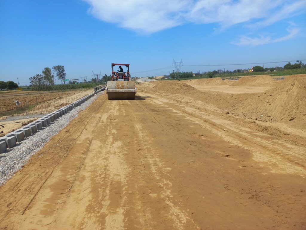
Method Statement for Earthwork (Embankment and Subgrade) Scope This work shall consist of embankment construction with approved material from roadway excavation or borrow pits. Reference IRC:SP:84-2014 MoRTH Specifications, Clause No. 305 IRC:36 Technical Specifications of Contract Equipment Excavator / Backhoe Dozer Motor Grader Dumpers Vibratory Roller Water Tanker Auto Level Measuring Tape Tools Hammer Crow Bar Spade Strings Pegs Lime Powder Manpower & Responsibilities Construction Manager Engineer / Supervisor Land Surveyor Material Engineer Safety Supervisor Helpers Construction Manager He shall be overall responsible for the activity including planning and organizing resources in consultation with the Project Manager. He shall ensure safety requirements, conduct relevant tests, maintain records, and coordinate with the consultant for approvals. Engineer / Supervisor Responsible for deploying resources, executing work as per drawings, maintaining quality as per specifications, and ensuring safety compliance. Also responsible for obtaining necessary approvals. Land Surveyor Responsible for establishing reference points, checking levels and alignment, recording completed work, and coordinating with the consultant for approvals. Material Engineer Responsible for implementing quality procedures, ensuring materials meet specifications, conducting tests, and maintaining records. Safety Supervisor Ensure that all activities are carried out safely as per the project safety plan. Materials Materials shall be free from logs, stumps, roots, rubbish, or any deleterious matter affecting stability. The material shall have: Liquid Limit (LL) less than 55% Plasticity Index (PI) less than 25% Free Swell Index less than 50% Minimum MDD of 15.2 kN/m³ as per IS:2720 Part-8 Samples from borrow areas shall be tested in the laboratory to verify these requirements. Procedures Before commencing earthwork, toe limits of embankment shall be marked. Original ground shall be leveled, scarified, watered, and compacted to achieve 95% of MDD. Material shall be excavated from borrow areas and transported by dumpers. Material shall be spread uniformly using grader/mechanical means. Clods shall be broken to maximum size of 75 mm. If NMC is less than OMC, water shall be added to maintain +1% to -2% of OMC. If NMC is more than OMC, material shall be dried by sun exposure. Compaction shall be done using vibratory roller (80–150 kN) to achieve 95% MDD. Rolling shall start from lower edge to upper edge. Each roller pass shall overlap 1/3rd of the previous pass. Acceptance Criteria Field dry density ≥ 95% of MDD Layer thickness tolerance ±25 mm Moisture content +1% to -2% of OMC during compaction Frequency of Testing Gradation Test (IS 2720 Part-4): 2 tests per 3000 cum Plasticity Test (IS 2720 Part-5): 2 tests per 3000 cum Density Test (IS 2720 Part-8): 2 tests per 3000 cum Deleterious Content (IS 2720 Part-27): As required Moisture Content (IS 2720 Part-2): 1 test per 250 cum CBR Test (IS 2720 Part-16): As required Field Compaction Testing One set of ten density measurements for every 3000 sqm or as required for statistical evaluation. Safety Measures All safety measures shall be followed as per approved EHS Plan. Frequently Asked Questions (FAQ) 1. What is the purpose of embankment construction? Embankment construction is carried out to raise the formation level of the road and provide a stable base for pavement layers. 2. What is the required compaction for embankment? The field dry density should be at least 95% of the Maximum Dry Density (MDD) as per MoRTH specifications. 3. What type of soil is suitable for embankment construction? Soil used should have Liquid Limit less than 55%, Plasticity Index less than 25%, and Free Swell Index less than 50%. 4. What is the optimum moisture condition during compaction? Moisture content should be maintained within +1% to -2% of Optimum Moisture Content (OMC) during compaction. 5. What equipment is commonly used in earthwork? Excavators, dumpers, graders, vibratory rollers, and water tankers are commonly used for embankment and subgrade work. 6. What is the maximum layer thickness allowed? Layer thickness tolerance is generally maintained within ±25 mm as per specifications. 7. Why is CBR testing important? CBR (California Bearing Ratio) test determines the strength of subgrade soil and its suitability for pavement design. 8. How frequently should field density tests be conducted? One set of ten density measurements is carried out for every 3000 sqm of compacted area or as required. 9. What are the key safety measures during earthwork? All activities must follow the approved EHS plan, including use of PPE, proper equipment handling, and safe working practices. 10. What is the role of a surveyor in earthwork? The surveyor establishes reference points, checks alignment and levels, and ensures the work is executed as per design.

Method Statement for Earthwork | Embankment and Subgrade Construction (MoRTH) Read More »

Earthwork

METHOD STATEMENT FOR SURVEY WORK

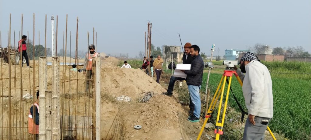
SCOPE: Survey Procedure Survey Sequence The survey is carried out from the starting point to the end point by following the sequence given below: Deriving of coordinates through DGPS. Running of traverse line between two known DGPS points. Reducing the relative levels between two known DGPS points. Staking in of topographical details in three-dimensional coordinates. Depicting of structural cross road details. Layout of reference line for roads and structures. Netting of original ground levels. Reference MoRTH Clause No: 109 and technical specifications of the project shall be followed. Equipments For the above task, the following precision survey instruments are used to maintain the required accuracy: DGPS (Dual Global Positioning System). Electronic Total Station with inbuilt programs (1″ least count accuracy). Auto Level with graduated vertical scale of 5 mm interpolation accuracy. Compass (to indicate North direction or true meridian) with 1 mm precision as directed by the Engineer. Tools Measuring Tape Pegs Nails Hammer Paint Tins Safety Cones Safety Boards Procedure Project reference center line of the proposed cross-section shall be fixed by the surveyor and marked on the ground using nails. Chainage shall be clearly marked on the existing road using paint. This marking shall be carried out at an interval of 20 m on straight portions and 10 m on curved portions. Offsets shall also be marked on the existing road wherever applicable. Further, prior to the commencement of earthwork or structural work, as per MoRTH specification Clause 109.3 and 109.5, the centerline shall be referenced by providing chainage pillars at the Right of Way (ROW) edge. Initial Survey Methodology Initial Survey (Satellite and Topographical) The survey is carried out for fixing of the control network. The following methodology is based on the measurement of angles and distances on a horizontal plane along with satellite geometry. GTS (Great Trigonometrical Survey) Great Trigonometrical Survey (GTS) points are already established by the Survey of India with reference to Mean Sea Level (MSL). DGPS Data (Dual Frequency Global Positioning System) Initially, pairs of ground control points are established at every 5 km interval. These points are connected to the DGPS network to obtain accurate X, Y, Z coordinates for the entire project. Traverse Traversing is carried out by measuring a set of horizontal angles in different quadrants between two straight points. Reciprocal horizontal distances between two points are measured by establishing traverse stations at every 200 m interval. An open traverse is carried out from a fixed DGPS station and closed at another fixed DGPS station. The coordinates (X, Y) are calculated and any misclosure in Easting and Northing is adjusted to maintain the required accuracy. Formula Δ Easting = Sin (North Bearing) × Horizontal Distance Δ Northing = Cos (North Bearing) × Horizontal Distance Double Territory Level Line Auto level instruments are used to determine the relative difference in elevation between two points. The survey is carried out between fixed DGPS datum points to identify misclosure in height. Precision automatic levels, conforming to MoRTH Clause 900 and fitted with micrometer attachments, shall be used for all double run and TBM transfer works to ensure accuracy. Temporary Bench Marks (TBM) Precast pillars of size 150 mm × 150 mm × 750 mm, reinforced with 6 mm bars and provided with a central 8 mm rod (marked with a dot on the top surface), are used as TBM pillars. These pillars are embedded such that 300 mm remains above ground level. Yellow, black, and red paints are used for marking their identification name and number. Traverse Station Traverse stations are marked by fixing a nail at the center and highlighting it with a yellow paint mark on one edge of the existing carriageway surface at every 250 m interval. Each station is assigned a unique identification number. Survey Details – OGL, Calibration & Safety Original Ground Level (OGL) The laid out reference line is taken as “0”. On the longitudinal section (L-section), cross-sections are taken at specified and prescribed offset distances on the original ground. Levels are observed at every 10 m interval in the longitudinal direction and up to PROW in the cross-sectional direction. The RLs (Reduced Levels) of OGL are observed and calculated from a known station and closed on another known station to ensure accuracy. Calibration Internal calibration shall be carried out once every month for leveling instruments and total stations in specified formats. Calibration certificates for level instruments and total stations must be submitted with valid certification from the manufacturer. A “Survey File” containing necessary data such as DGPS details, traversing details, horizontal and vertical control points, reference pillars, survey monuments, and horizontal alignment setting-out details shall be submitted to the Client/Engineer. Responsibility The responsibility for implementation of this procedure lies with the surveyors deployed at various sections for different activities, along with the Survey Engineer and Section In-Charge. Safety Precautions Do not aim the telescope at the sun, as it may damage the EDM of the instrument. Never place the instrument directly on the ground, as it may damage the base. Do not carry instruments along with the stand from one station to another. All safety measures shall be followed as per HIRA (Hazard Identification and Risk Assessment). Avoid heavy shocks and vibrations to the instruments. Remove the battery before storing the instrument in its case. Do not store wet instruments inside the case; allow them to dry before storage. Before removing the instrument from the case, note the layout position to place it back correctly. All staff and workmen shall wear reflective jackets and PPE at the work area. A minimum of 6 cones and a “Men at Work” signboard shall be used during survey work on roads. Staff and workmen shall not use mobile phones while moving on the road. Required safety equipment shall be provided at site to ensure safe working conditions.

METHOD STATEMENT FOR SURVEY WORK Read More »

Survey

Wet Aggregate Impact Value Test | IS Procedure & Calculation

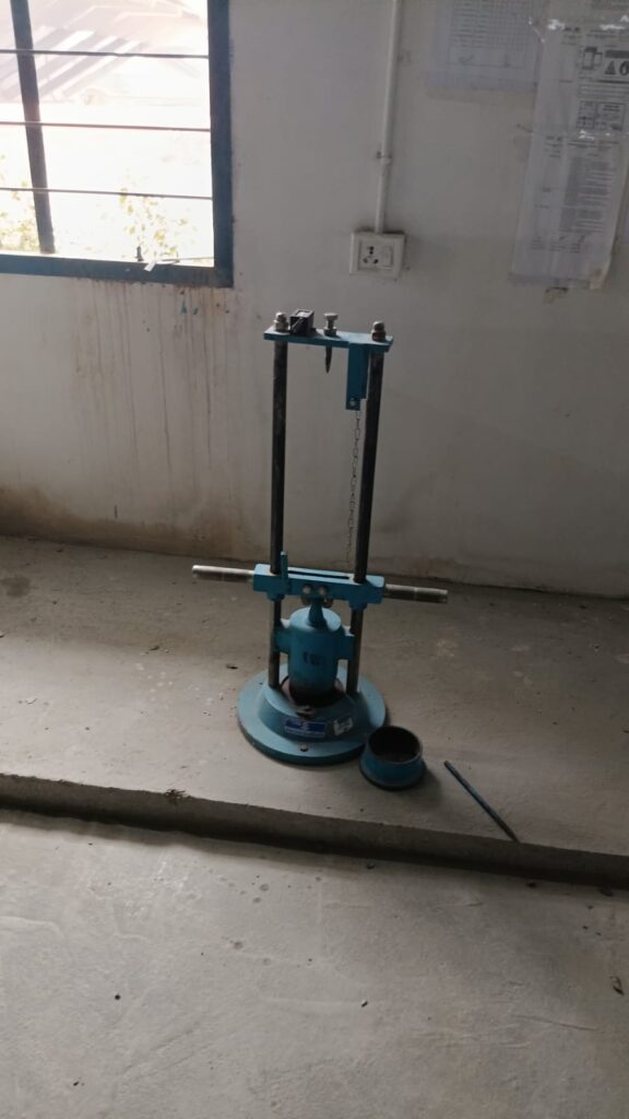
Wet Aggregate Impact Value Test OBJECT To determine the Aggregate Impact value of coarse Aggregate. APPARATUS AIV machine, IS Sieve 12.5mm, 10.0mm, 2.36mm, Oven, Brush, Balance 0.1 gm accuracy. PROCEDURE The test sample shall consist of aggregate the whole of which passes a 12.5-mm IS Sieve and retained on 10 mm IS Sieve. The aggregate comprising the test sample shall be dried in an oven for a period of four hours; the weight becomes constant at a temperature of 105 to 110°C and cooled. The measure shall be filled about one-third full with the aggregate and tamped with 25 strokes of the rounded end of the tamping rod. A further similar quantity of aggregate shall be added and a further tamping of 25 strokes given. The measure shall finally be filled to overflowing, tamped 25 times and the surplus aggregate struck off, using the tamping rod as a straight-edge. The net weight of aggregate in the measure shall be determined to the nearest gram (weight A) and this weight of aggregate shall be used for the duplicate test on the same material. This oven-dried sample is immersed in water for three days. Wet sample after the immersion period is surface dried by suitable cloth. The cup shall be fixed firmly in position on the base of the machine and the whole of the test sample placed in it and compacted by a single tamping of 25 strokes of the tamping rod. The hammer shall be raised until its lower face is 350 mm above the upper surface of the aggregate in the cup, and allowed to fall freely onto the aggregate. The test sample shall be subjected to a total of 15 such blows each being delivered at an interval of not less than one second. The crushed aggregate shall then be removed from the cup and the whole of it sieved on the 2.36 mm IS Sieve and washed with water till no further significant amount passes in one minute. The fraction retained on the sieve shall be dried in an oven to the constant weight at 105 to 110°C and weighed to an accuracy of 0.1 g (weight B). The fraction retained on the sieve (weight B) shall be subtracted from the weight of the original oven dried sample (weight A). The resultant weight (weight A – weight B) shall represent the fraction passing 2.36 mm IS Sieve (weight C). Two tests shall be made. CALCULATION Aggregate Impact Value = (C / A) × 100 Where: C = Weight of fines formed A = Weight of the oven-dried sample

Wet Aggregate Impact Value Test | IS Procedure & Calculation Read More »

Aggregate

Procedure for Sampling & Testing of Incoming Materials (QA/QC Highway Works)

SAMPLING AND TESTING PROCEDURE FOR CEMENT: Check the seal number as per invoice of the browser. If the seal found tight and match with the invoice, then collect a representative sample of 20kg for in-house testing in the presence of client. Conduct the routine test like fineness, % passing on 90 mic sieve and allow for unload, if found complied to IS 4031. The tests like consistency, soundness, compressive strength, initial and final setting of the cement shall be tested as per IS 4031. Prepare formats for above tests and get it signed by client and file the records. Maintain invoice register for cement receipt at plant. Ensure all the tests shall be performed as per week number of the cement. SAMPLING AND TESTING OF REINFORCEMENT: Once the reinforcement lots arrived to site from approved sources, unload the material in stacking yard. Inspect the reinforcement lot as per invoice and ensure tagging of reinforcement for every lot. Collect 2 samples (3 pieces of 1m length for each sample) from every dia of reinforcement for a lot of 50t and 3 samples for 100MT. Bring the cutting pieces to lab and in the sampling register. Check the weight per running meter for the samples collected. Rolling margin of all samples shall be collected for every lot. If the rolling margin found within the tolerable limits as per IS 1786-2008, accept the lot. Otherwise inform to supplier to take back the lot. Invoice with test certificate shall be verified by quality in charge and sign on test certificate. Enter the details of reinforcement received in the invoice register and get the signature of client. If any lot required for independent lab testing, raise RFI and collect the samples in the presence of client. Sign the sample card by client and IE representatives and keep one copy in lab and other copy to tie for sample pieces. Physical and chemical properties of the reinforcement tested in independent lab shall be reviewed by quality in charge and client and ensure complied to IS 1786-2008. The test reports of independent lab will be submitted to client for review and approval. SAMPLING AND TESTING OF FINE AGGREGATE: Once the fine aggregate (river sand) load received at site from approved source, collect a representative sample of 20kg for lab testing to check physical properties. Enter the details of river sand in the sampling register. The material shall be tested for sieve analysis and check for zone of the sand and Fineness Modulus (FM). Check the silt content of the sand as per IS 2386. If the sand falls in zone-II and the FM lies in between 2 to 3.5 and the silt content less than 3% , the vehicle shall be allowed for unloading . If the sand doesn’t meet the above requirements (FM and silt content) shall be rejected. If the sand contains over size material more than 10% on 10mm sieve shall be screened and use for permanent works. Independent lab testing of sand shall be tested as per approved ITP. SAMPLING AND TESTING OF BITUMEN: Once the bitumen tanker arrived at site, verify the invoice number and seal of the tanker. Collect the sample with sampler of weight not less than 1 kg. Enter the sample details in sampling register and sample number shall be given. Test the sample for absolute viscosity, softening point, and penetration. If the test results found satisfactory, allow the tanker for unload. Review the conducted test results and compare with MTC. Prepare the test reports and get it signed by client and file the records. Maintain the invoice register for incoming bitumen and get the signature in theregister by client. The sample shall be collected for independent lab testing frequency as per theapproved ITP. SAMPLING AND TESTING OF ADMIXTURE: Once the admixture barrels arrived at site, verify the invoice number and batch number of the material. Collect the sample with sampler of weight not less than 2 kg. Enter the sample details in sampling register and sample number shall be given. Test the sample for density at room temperature. If the test results found satisfactory, then allow the admixture to use in permanent work. Review the MTC test results as per IS 9103. Maintain the invoice register for incoming bitumen and get the signature in the register by client. SAMPLING AND TESTING OF EMULSION (SS-1 & RS-1): Once the emulsion tanker arrived at site, verify the invoice number and seal of the tanker. Collect the sample with sampler of weight not less than 1 kg. Enter the sample details in sampling register and sample number shall be given. Test the sample for viscosity by say bolt furl viscometer. If the test results found satisfactory, allow the tanker for unload. Conduct the balance tests like residue test by evaporation. Review the conducted test results and compare with MTC. Prepare the test reports and get it signed by client and file the records. Maintain the invoice register for incoming emulsions and get the signature in the register by client. The sample shall be collected for independent lab testing frequency as per the approved ITP. SAMPLING AND TESTING OF GEO-GRIDS / GEO-TEXTILE: Once the Geogrid material arrived at site, verify the invoice number and grade. Raise the RFI and Collect the sample from bundle I roll of size not less than 2m*2m from each grade. Enter the sample details in sampling register and sample number shall be given. Count the number of ribs in machine direction and transverse direction. The samples shall be tagged with sample card mentioned all the details with signatures of client. The collected samples shall be sent for independent lab testing as per approved ITP. Review the MTC test results as per grade requirement. Maintain the invoice register for Geogrid and get the signature of client. TEST PROCEDURE OF CTSB MIX DESIGN Raise RFI for sampling of aggregates for CTSB Mix Design. Sample the individual aggregates jointly. Do individual gradation for each aggregate as mentioned in MoRTH

Procedure for Sampling & Testing of Incoming Materials (QA/QC Highway Works) Read More »

Soil

Method Statement for Dismantling Culverts, Bridges, Pavements and Other Structures

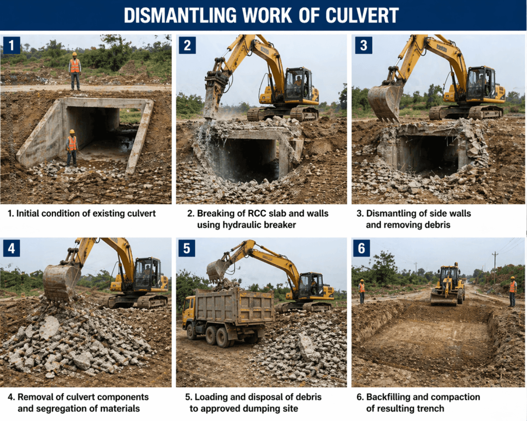
Method Statement for Dismantling Culverts, Bridges, Pavements and Other Structures [last_updated] 1. Purpose The purpose of this Method Statement is to define the detailed construction methodology for dismantling culverts, bridges, pavements, kerbs, and other structures in accordance with the provisions of MoRTH Clause 202 and relevant amendments in the Technical Specifications. 2. Scope of Work The work shall consist of removing existing culverts, bridges, pavements, kerbs, and other structures that interfere with new construction activities or are unsuitable to remain in place. The work shall also include salvaging, disposal of dismantled materials, and backfilling of resulting trenches and pits. Existing structures located within the highway limits and designated for removal shall be dismantled up to the extent shown in the Good for Construction (GFC) drawings or as directed by the Authority Engineer. Dismantling operations shall be carried out using suitable equipment such as backhoe loaders, excavators, dozers, graders, tractor dozers, jackhammers, or excavators fitted with rock breakers, depending upon the type of structure. Care shall be taken to avoid disturbance or damage to adjacent pavements, structures, underground utilities, and any work intended to remain in place. All dismantling operations that may affect new construction shall be completed before commencement of new works. Traffic diversion, safety arrangements, and traffic management measures shall be implemented as per approved methodology prior to dismantling activities. Dismantling work shall commence only after obtaining approval from the Authority Engineer. 3. Sequence of Operations 3.1 Dismantling of Culverts and Bridges Existing culverts and bridges shall be dismantled carefully to prevent damage to reusable materials, portions of structures to be retained, nearby properties, and adjacent structures. Where existing culverts or bridges are to be extended or incorporated into the new work, only the required portion shall be removed as directed by the Authority Engineer. Connecting edges shall be cut, chipped, and trimmed to the required alignment and levels without weakening the remaining structure. Reinforcement bars intended for future connection as dowels or ties shall be protected from damage during dismantling operations. Pipe culverts shall be dismantled carefully to avoid breakage or damage to the pipes. 3.2 Dismantling of Pavements and Other Structures Existing pavements, kerbs, gutters, and other structures shall be dismantled as specified in the drawings and Technical Specifications. Portions intended to remain in service shall be cut neatly along straight lines or existing joints with faces perpendicular to the pavement surface. Sufficient dismantling shall be carried out to achieve proper grades, alignment, and connection with the proposed works. Concrete pavements, bituminous pavements, shoulders, and base courses designated for dismantling shall be broken into pieces not exceeding 0.02 cubic metres. Dismantled materials shall either be stockpiled at approved locations for reuse or disposed of as directed by the Authority Engineer. Holes, depressions, and excavated areas resulting from dismantling operations shall be backfilled using approved material and compacted to the specified density. Disposal of dismantled materials shall be carried out in accordance with the relevant Technical Specifications and environmental requirements. 4. Equipment Used Backhoe Loader Excavator Bull Dozer Tractor Dozer Motor Grader Jack Hammer Excavator with Rock Breaker

Method Statement for Dismantling Culverts, Bridges, Pavements and Other Structures Read More »

Concrete Work
borrow sampling

Borrow Area Method Statement as per MoRTH | QA/QC Construction Procedure

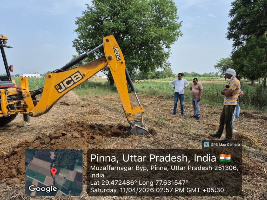
      METHOD STATEMENT FOR BORROW AREA Scope  This method Statement covers the work involved in obtaining borrow Material for work under this contract, including negotiations with owners of the land on which borrow areas are situated, cleaning the site, stripping and disposing of excess overburden, excavating selected material for use in the work, and finishing –off the borrow areas. Reference  MoRT&H Specification clause No 301 to 303 and technical specification of contract Equipment  Excavators, Dumpers Negotiations with owners and authorities  We shall be responsible for all negotiations with and compensation of owners for all borrow area that we shall identify and prescribe. However, for those that are identified are prescribed by the employer consultants, we shall exempted from all obligations and costs in respect of negotiations with and compensations of the owners of the land on which the borrow area situated. Use of Borrow area  Having concluded verbally and in written all the necessary negotiations with the owners of the ground on which any borrow area is situated. We shall open such a borrow area. The notification to the land owners will be at least 7days before prospecting and the engineer will also informed accordingly. Obtaining Borrow area material General  The arrangement for the source of supply of the material for embankment and sub grade and compliance with the guidelines, and environmental requirements, in respect of excavation and borrow area as stipulated from time to time by the ministry of Environmental and forests, government of India and the local bodies, as applicable shall be sole responsibility of the contractor  Borrow pits along the road shall be discouraged. If permitted by the engineer, these shall not be dug continuously. Ridges of not less than 8m width should be left at intervals not exceeding 300m. Small drains shall be cut through the ridges to facilities drainage. The depth of the pits shall be so regulated that their bottom does not cut an imaginary line having a slope of 1 vertical to 4 horizontal projected from the edge of the final section of the bank, the maximum depth in any case being limited to 1.5 m. also, no pits shall be dug within the offset width of a minimum of 10m  Borrow material shall be obtained from approved sources of supply listed and described on the borrow area plans. Or from such other sources as may from time to time be tested and approved by the engineer. Use for Borrow area material  The decision as to which source of supply of borrow material shall be used at any time shall rest with the engineer, and we shall at any stage of work use that approved source of supply which in the opinion of the engineer is the most suitable in regard to the quality and quantities of the various types of available materials and the ultimate cost of the work to the employee.  Should there be need to obtain material from sources other than those shown on the borrow area schedule, we shall excavate the necessary trail holes, and take such samples and conduct or have conducted such tests as are deemed to be necessary by the engineer, we shall submit the results and sufficient details to the engineer to satisfy him that the quality and quality of the material available in the proposed borrow area are acceptable for the intended use, all at our own expense. Compensation to owners and arrangements for taking any material shall be In terms of the project specification.  Approval of borrow area shall apply only to those portions of the area from which acceptable material can be obtained or produced. We shall organelles our operations in any approved borrow area or portions thereof with a view to using the material for the purpose envisaged.  We shall plan our exploitation of the borrow area in such a manner that the various types of materials excavated can be selected and loaded directly for use. When this is unfeasible for reasons beyond our control, material to be stockpiled for later use shall be loaded, transported and temporarily stockpiled as ordered by the engineer and as determined in clause 3203 of SATCC specifications. No material reversed for a specific purpose shall be used for any other purpose without the written approval of the engineer.  Where suitable sources of materials are available in existing cuttings and side drains, or anywhere else in the road prism or within the road reverse boundaries, such material shall be used for the construction of fills, pavement layers and shoulders, if approved by the engineer. Opening and working on Borrow area and Haul Roads Removing topsoil  Prior to opening a borrow area; we shall ascertain from the engineer whether the removal to topsoil is required and shall then remove and stockpile such topsoil as instructed by the engineer. This work shall be carried out, measured and paid for in accordance. Clearing and grubbing  Clearing and grubbing of borrow area will be measured of payment in accordance with the provisions before excavation is commenced, but only in the following cases, unless otherwise directed by the engineer (i) In borrow area located in paginations. (ii) In borrow area where large trees with trunk exceeding 1.0 m in circumference (iii) Borrow area without any excess overburden but where the removal of grass shrubs and roots is required. Unless the cleaning and grubbing of a borrow area have been prescribed by the engineer in writing, no payment will be made for cleaning and grubbing such borrow area. Thos applies practically to borrow areas opened for obtaining rock or sand used in the construction of stone-pitching, concrete work, crushed-stone base or sub-base permeable subsurface drain material or surfacing. Excess overburden  We shall advise the engineer in good time, before any excavation at such borrow area is commenced, of his intension of staffing to use a borrow area in order that a survey of

Borrow Area Method Statement as per MoRTH | QA/QC Construction Procedure Read More »

Soil

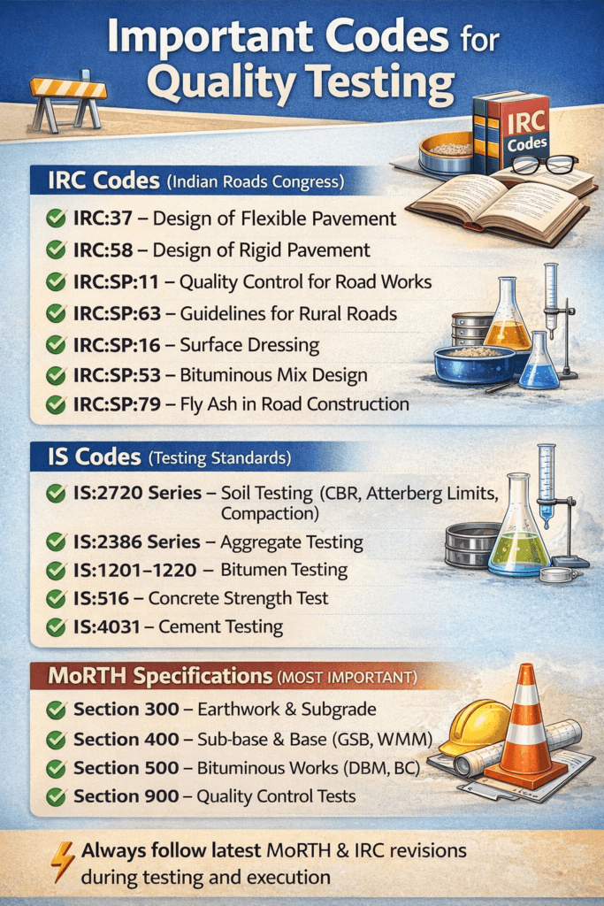
Important IS & IRC Codes for Highway Engineers

Important IS & IRC Codes for Highway, Site and QA/QC Lab Engineers ⚡ Quick Summary ✔ Complete reference to the most important IS & IRC codes used in civil and highway material testing. ✔ Find the correct standard for testing concrete, aggregates, soil, bitumen, cement, steel, and pavement materials. ✔ Ensure compliance with MoRTH, IRC, NHAI, and project quality requirements. ✔ Reduce testing errors by selecting the appropriate IS/IRC code for every laboratory and field test. ✔ A practical guide for QA/QC engineers, material engineers, consultants, contractors, and engineering students. Standards and codes play a crucial role in ensuring quality and uniformity in highway construction. Every QA/QC Engineer must have basic knowledge of IS Codes, IRC Guidelines, and MoRTH Specifications to ensure proper testing and execution. 🌍 IS 2720 – Soil Testing IS 2720 (Part 1) – Preparation of soil samples IS 2720 (Part 2) – Moisture content IS 2720 (Part 3) – Specific gravity IS 2720 (Part 4) – Grain size analysis IS 2720 (Part 5) – Liquid limit IS 2720 (Part 5) – Plastic limit IS 2720 (Part 7) – Standard Proctor Test IS 2720 (Part 8) – Modified Proctor Test IS 2720 (Part 10) – UCS Test IS 2720 (Part 16) – CBR Test IS 2720 (Part 28) – Sand Replacemet Method IS 2720 (Part 40) – Free Swell Index Test 👉 Use: Subgrade and earthwork quality control 🪨 IS 2386 – Aggregate Testing IS 2386 (Part 1) – Sampling of aggregates, Flakiness & elongation index IS 2386 (Part 2) – Deleterious materials IS 2386 (Part 3) – Specific gravity & water absorption IS 2386 (Part 4) – AIV, ACV, Crushing Value IS 2386 (Part 5) – Soundness of Aggregate 👉 Use: GSB, WMM, DBM & Concrete works 🛢️ IS 1200 Series – Bitumen Testing IS 1201 – Sampling of bitumen IS 1202 – DETERMINATION OF SPECIFIC GRAVITY IS 1203 – DETERMINATION OF PENETRATIONt IS 1205 – DETERMINATION OF SOFTENING POINTt IS 1206 (Part 2) – DETERMINATION OF VISCOSITY: PART II ABSOLUTE VISCOSITY IS 1206 (Part 3) – DETERMINATION OF VISCOSITY : PART III KINEMATIC VISCOSITY IS 1208 – DETERMINATION OF DUCTILITY IS 1209 – DETERMINATION OF FLASH POINT AND FIRE POINT IS 1211 – Water content 👉 Use: Bituminous layers (DBM, BC, SDBC) 🧱 IS 4031 – Cement Testing IS 4031 (Part 1) – Fineness IS 4031 (Part 3) – Soundness Test IS 4031 (Part 4) – Standard consistency IS 4031 (Part 5) – Setting time IS 4031 (Part 6) – Compressive Strength 👉 Use: Concrete and structural works 📘 MoRTH Specifications for Road & Bridge Works Official technical specifications published by the Ministry of Road Transport and Highways (MoRTH) for the construction and maintenance of roads and bridges in India. Defines requirements for materials, workmanship, construction procedures, quality control, acceptance criteria, testing frequency, and permissible tolerances. Forms the primary contractual reference for NHAI, State Highway Authorities, EPC, HAM, BOT, and O&M highway projects. Works together with IRC Standards and relevant IS Codes to ensure quality, safety, durability, and compliance throughout the project lifecycle. 👉 Primary Use: Material approval, construction methodology, laboratory and field testing, quality assurance (QA), quality control (QC), inspection, measurement, and acceptance of highway works. 🛣️ IRC Standards & Guidelines Published by the Indian Roads Congress (IRC), the apex technical body for road and bridge engineering standards in India. Provides comprehensive standards for geometric design, pavement design, traffic engineering, road safety, bridges, drainage, maintenance, and rehabilitation. Includes recommended practices, design criteria, testing procedures, and construction guidelines for national and state highway projects. Used in conjunction with MoRTH Specifications and relevant IS Codes to achieve technically compliant and high-quality highway infrastructure. 👉 Primary Use: Highway planning, pavement design, construction, maintenance, road safety, material testing, and quality assurance (QA/QC). ⚠️ Important Note Always use the latest revisions of IS Codes, IRC Standards, and MoRTH Specifications applicable to your project or contract. Superseded or outdated standards may result in non-compliance, failed inspections, rework, delayed approvals, or rejection by the Engineer/Authority. 💡 Best Practice: Before conducting any laboratory or field test, verify the applicable MoRTH Clause, corresponding IRC Standard, and relevant IS Code. Maintain updated digital and printed copies of these standards for quick reference during testing, inspections, quality audits, and project execution.

Important IS & IRC Codes for Highway Engineers Read More »

FAQ/Interview

Top QA/QC Site Mistakes Engineers Must Avoid

Top QA/QC Site Mistakes Engineers Must Avoid ⚡ Quick Summary ✔ Identify common QA/QC mistakes ✔ Understand their impact on projects ✔ Learn how to avoid costly errors ✔ Improve overall site quality Mistakes in QA/QC can lead to serious consequences such as project delays, rework, financial loss, and even structural failure. Understanding these common errors will help you become a more efficient and reliable site engineer. ❌ Skipping Material Testing Ignoring required tests can result in using poor quality materials on site. Impact: Weak structure, early failure Solution: Always follow testing frequency as per specifications ❌ Improper Compaction Inadequate compaction reduces strength of soil and pavement layers. Impact: Settlement, cracks, pavement failure Solution: Ensure proper rolling and density checks (FDT) ❌ Using Unapproved Materials Using materials without approval or testing can compromise quality. Impact: Rejection of work, penalties Solution: Use only approved and tested materials ❌ Poor Documentation Missing or incorrect records can lead to rejection even if work is good. Impact: Audit issues, claim rejection Solution: Maintain proper and updated records ❌ Ignoring Specifications Not following MoRTH/IS codes leads to non-compliance. Impact: Work failure and re-execution Solution: Always follow approved drawings and specifications ⚠️ Key Takeaway Most site failures happen due to small mistakes repeated daily. A disciplined QA/QC system can prevent major losses. 💡 Pro Tip: Test → Record → Approve → Then Execute ⚠️ Free Download Get QA/QC Checklist to avoid common site mistakes Download Checklist 🔒 Want Complete QA/QC System? Unlock SOPs, checklists, formats & advanced tools used by professionals Upgrade to Starter Bundle @299

Top QA/QC Site Mistakes Engineers Must Avoid Read More »

FAQ/Interview

© 2026 HIGHWAY QUALITY TEST. All rights reserved.

WhatsAppNeed Help?
Scroll to Top